
OLED display panel

A display panel and display area technology is applied in the field of OLED display panels to achieve the effects of improving device life, delaying water and oxygen intrusion, and improving light transmittance

Inactive Publication Date: 2019-07-12
WUHAN CHINA STAR OPTOELECTRONICS SEMICON DISPLAY TECH CO LTD
View PDF10 Cites 36 Cited by
  • Summary
  • Abstract
  • Description
  • Claims
  • Application Information

AI Technical Summary

Problems solved by technology

[0004] However, since the cathode tiles the display panel, the cracks generated by the cathode expand into the display area during the hole digging process.
[0005] Therefore, the existing full-screen technology has the technical problem that the cracks generated by the cathode when digging holes expand into the display area, which needs to be improved.

Method used


Image

  • OLED display panel
  • OLED display panel
  • OLED display panel

Examples


Embodiment Construction

[0030] The following descriptions of the various embodiments refer to the accompanying drawings to illustrate specific embodiments in which the invention may be practiced. The directional terms mentioned in the present invention, such as [top], [bottom], [front], [back], [left], [right], [inside], [outside], [side], etc., are only for reference The orientation of the attached schema. Therefore, the directional terms used are used to illustrate and understand the present invention, but not to limit the present invention. In the figures, structurally similar elements are denoted by the same reference numerals.

[0031] The embodiment of the present invention can alleviate the technical problem of the existing full-screen technology that the crack generated by the cathode when digging holes propagates into the display area.

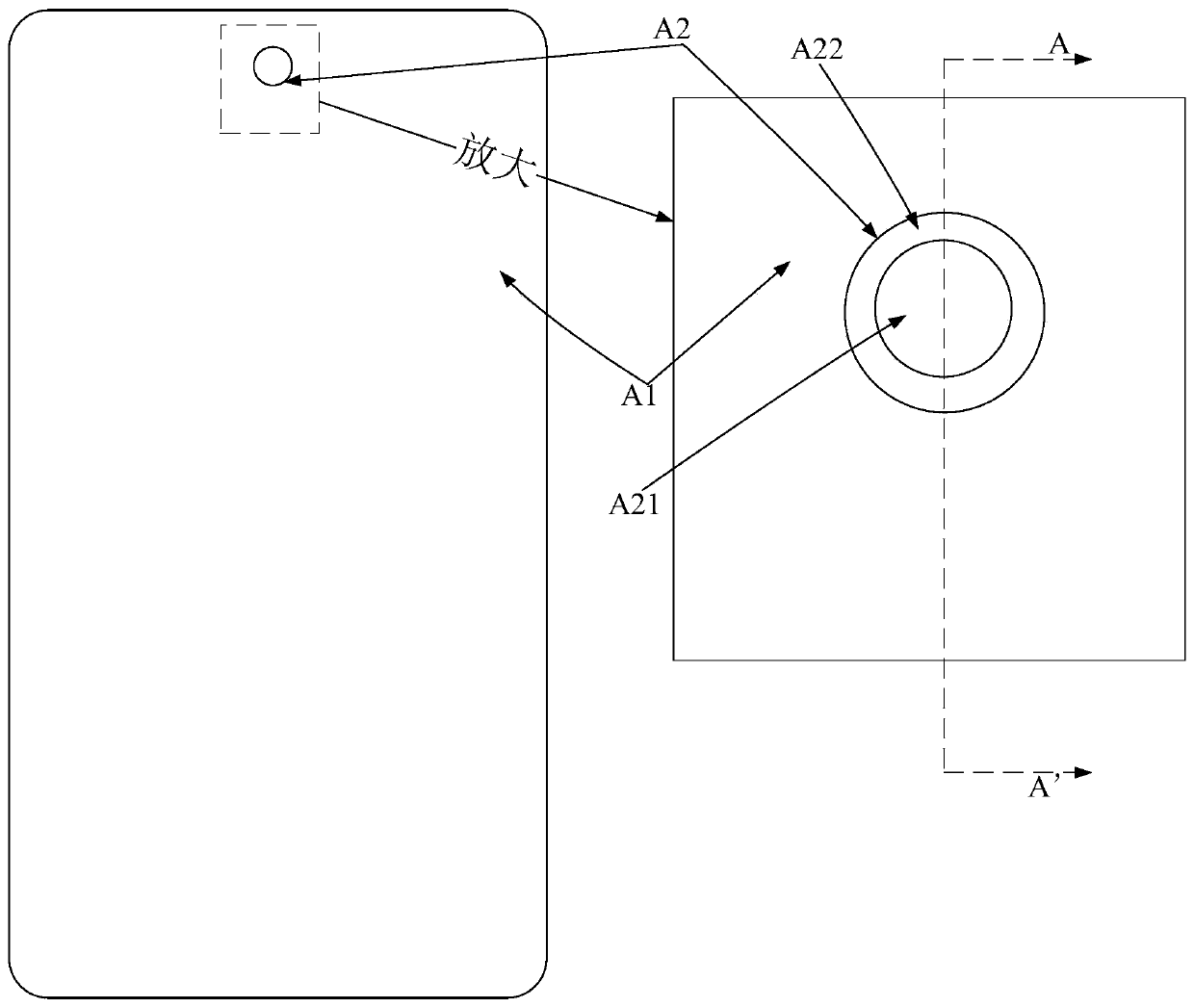
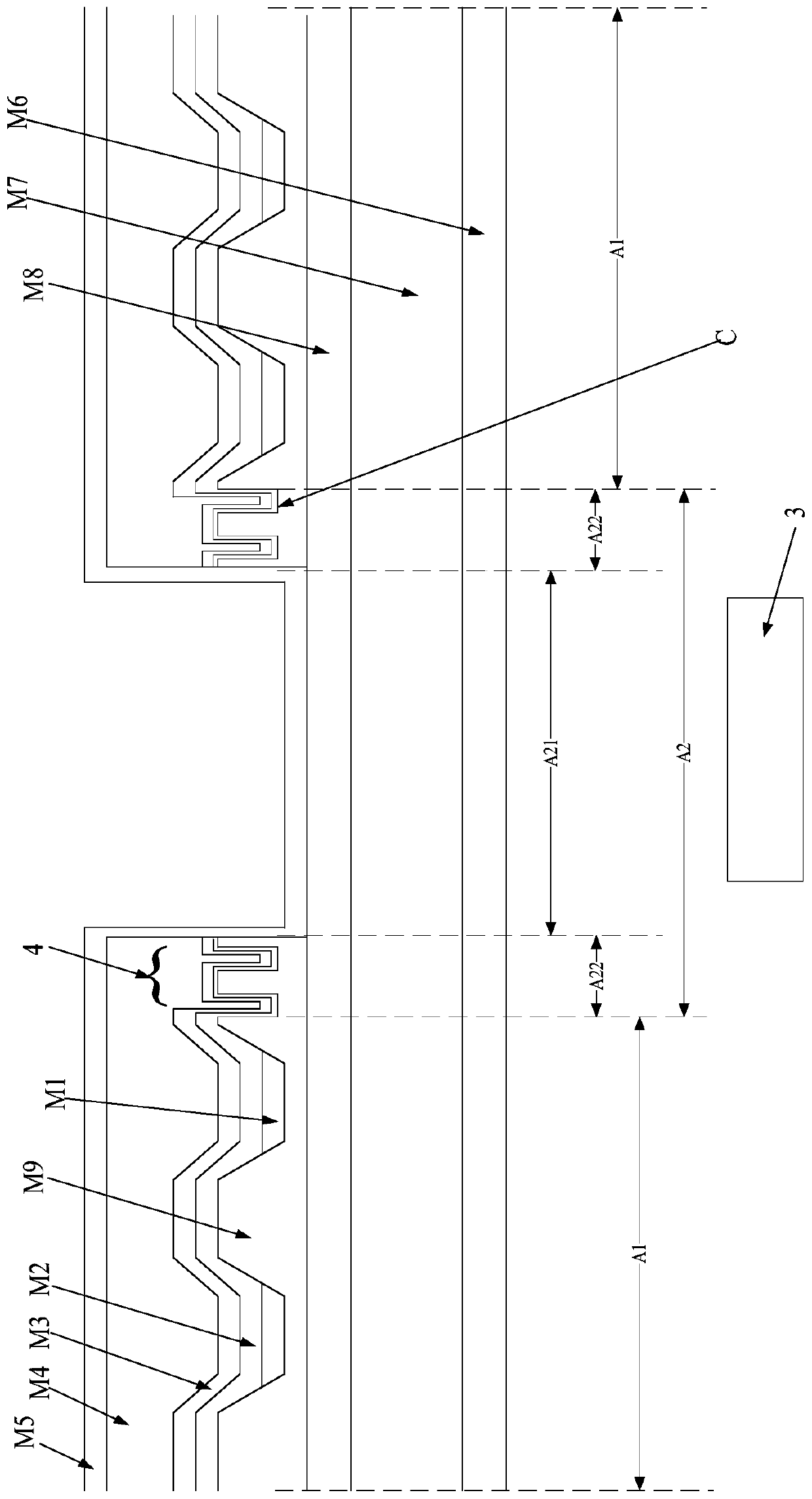
[0032] In one embodiment, as Figure 2 to Figure 6 As shown, the OLED display panel provided by the embodiment of the present invention includes a displa...


PUM


Abstract

The invention provides an OLED display panel. The OLED display panel comprises an electronic element setting area corresponding to an electronic element setting position, wherein the electronic element setting area comprises a light transmission area and a buffer area, and a micro-nano structure is formed in the buffer area; according to the invention, the micro-nano structure is arranged in the buffer area between the light transmission area and the display area, and can prevent cracks generated by a common electrode layer such as a cathode from expanding to the display area when holes are dug by laser cutting or other processes, so that the technical problem is solved that the cracks generated by the cathode when the holes are dug expand to the display area in the conventional comprehensive screen technology, and the micro-nano structure can delay water and oxygen invasion of the side surface of the hole digging area in the hole digging process, so that the service life of the deviceis prolonged finally.

Description

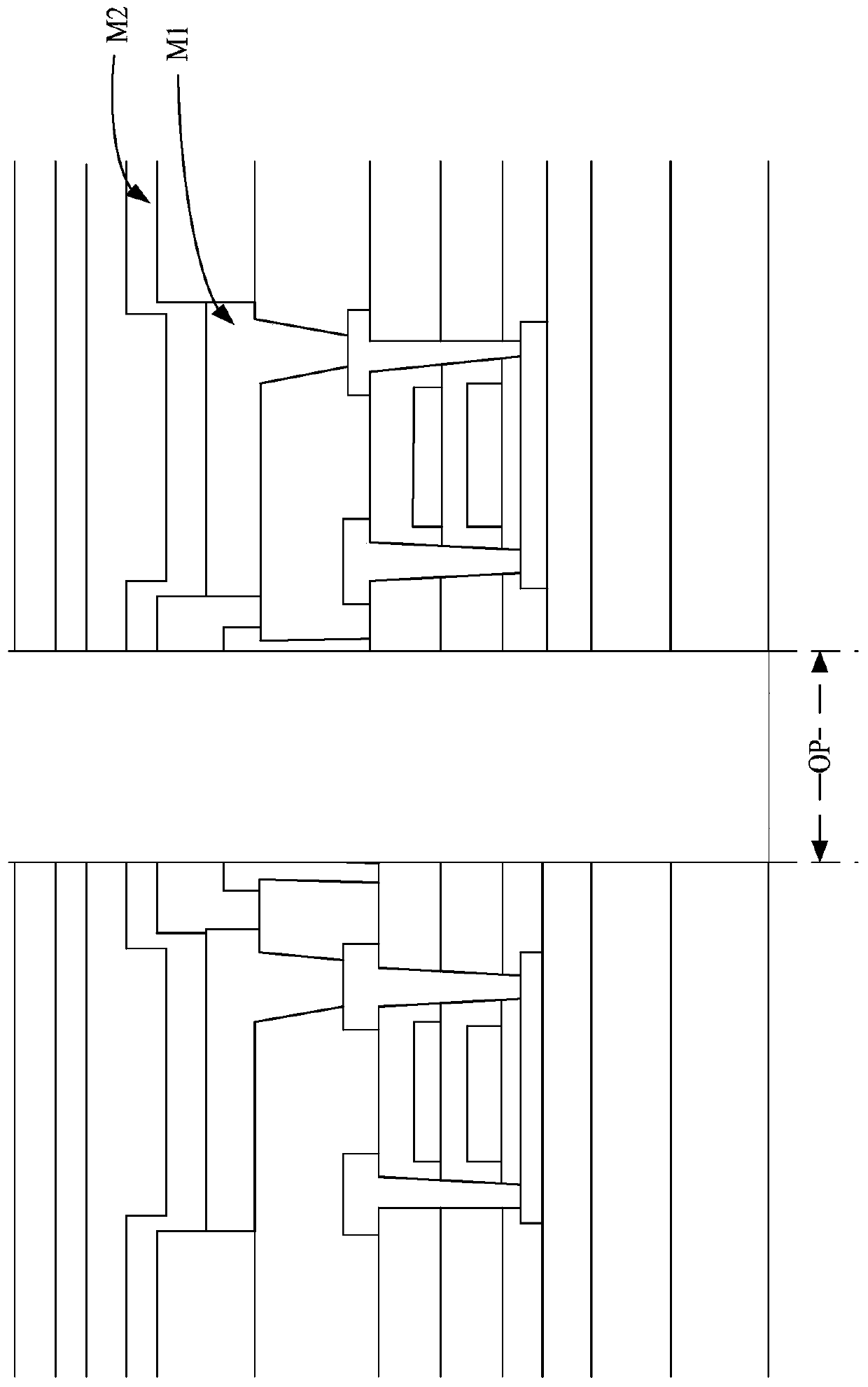
technical field [0001] The invention relates to the field of display technology, in particular to an OLED display panel. Background technique [0002] With the development of full-screen technology, the technology of placing electronic components such as cameras under the screen under the display screen is a development trend. The cathode tile display panel of the existing OLED (Organic Light Emitting Diode, Organic Light Emitting Diode) display panel is made of magnesium-silver alloy or magnesium-silver laminated structure. When passing through the cathode, the loss is more. [0003] Therefore, if figure 1 As shown, in the prior art, in order to ensure the lighting effect of the electronic components under the screen, such as the camera, it is necessary to remove the light-emitting functional layer (including the anode M1, the light-emitting layer and the cathode M2, etc.) above the camera to form a light-transmitting area (ie figure 1 In the OP area), that is, digging t...

Claims


Application Information

Patent Timeline
Patent Type & Authority Applications(China)
IPC IPC(8): H01L27/32H01L51/52
CPCH10K59/00H10K50/80H10K50/84
Inventor 张文智
Owner WUHAN CHINA STAR OPTOELECTRONICS SEMICON DISPLAY TECH CO LTD
Learn More