Node deviation measuring instrument, manufacturing method thereof and method for measuring node deviation

A technology of deviation measurement and manufacturing method, which is applied in the field of shipbuilding and can solve the problems of poor generality of node deviation measuring instruments, inability of nodal deviation measuring instruments to measure the continuous state cross joints of intermediate plates, etc.

Active Publication Date: 2021-02-26
SHANGHAI WAIGAOQIAO SHIP BUILDING CO LTD
View PDF10 Cites 0 Cited by
  • Summary
  • Abstract
  • Description
  • Claims
  • Application Information

AI Technical Summary

Problems solved by technology

[0007] The technical problem to be solved by the present invention is to overcome the defect that the node deviation measuring instrument in the prior art cannot measure the cross joint in the state where the intermediate plate is continuous, resulting in poor versatility of the node deviation measuring instrument, and to provide a node deviation measuring instrument, Its production method and measurement method of node deviation

Method used


Image

  • Node deviation measuring instrument, manufacturing method thereof and method for measuring node deviation
  • Node deviation measuring instrument, manufacturing method thereof and method for measuring node deviation
  • Node deviation measuring instrument, manufacturing method thereof and method for measuring node deviation

Examples


Embodiment 1

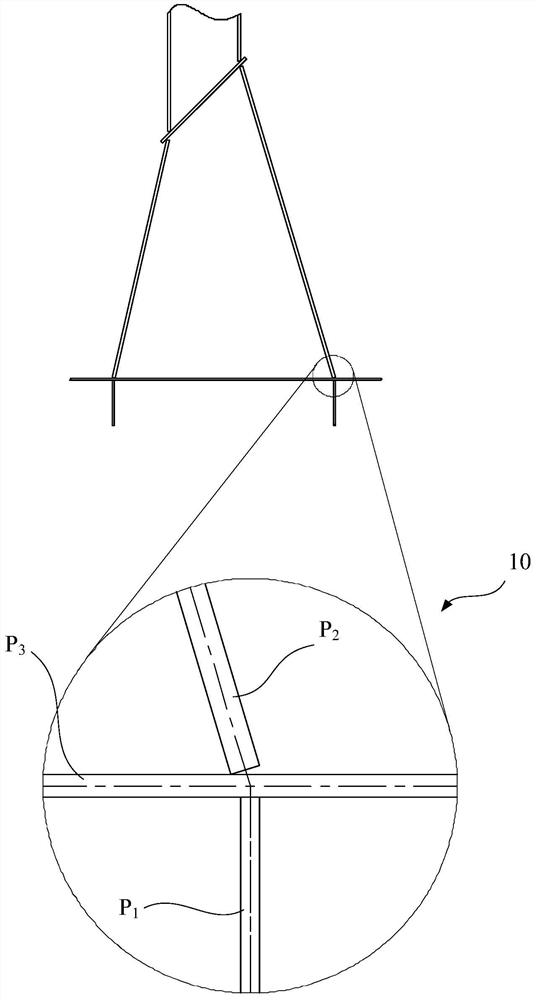
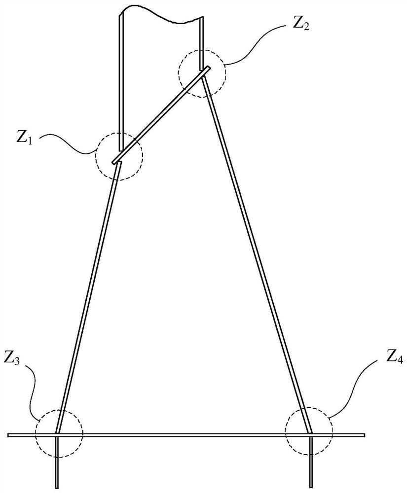
[0075] Such as image 3 As shown in the figure below, multiple cross joints (Z 1 ,Z 2 ,Z 3 ,Z 4 ) as an example, in this embodiment, first take the discontinuous cross joint Z of the middle plate (the third plate) 1 As research target.

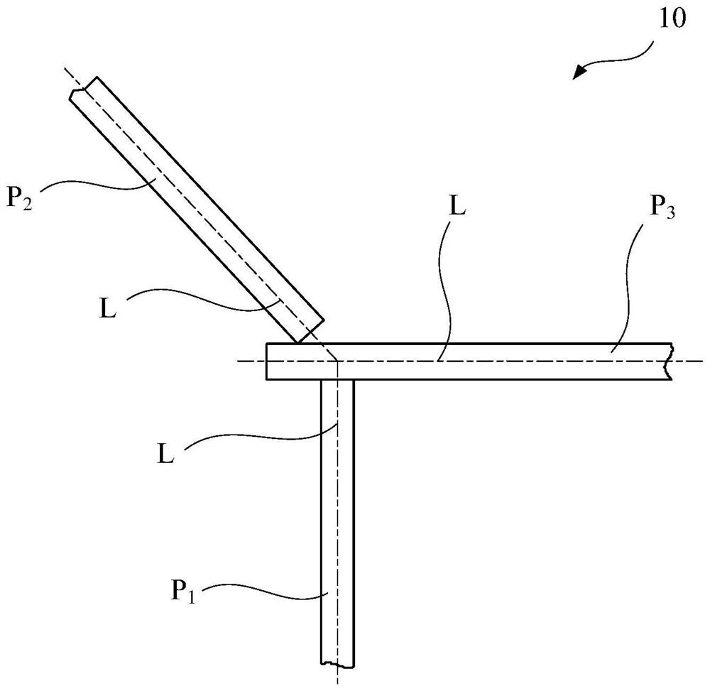
[0076] Step 1: For the convenience of observation, the node Z 1 Zoom in, and mark the centerlines of the first plate, the second plate and the third plate and the angle between them on the same side, that is, the angle β between the first plate and the third plate, and the angle between the second plate and the third plate angle θ, assuming that their center lines intersect at a point, see Figure 4 .

[0077] Step 2: Based on the state when the centerlines of the three boards intersect at one point, take their intersection point as the base point, and synchronize their centerlines as a whole along the centerline L of the first board 1 move down and make the centerline of the third plate L 3 coincides with its lower edge, see Figure...

Embodiment 2

[0095] for image 3 Cross fitting Z shown in 3 and Z 4 , since its third plate (middle plate) is continuous, it cannot be reused as Figure 8 The right edge of the first plate and the lower edge of the third plate of the illustrated cross joint hold the node deflection gauge 20 .

[0096] Such as Figure 10 As shown, in this embodiment, the cross joint Z 4 as an example. In this case, the upper surface of the third plate (middle plate) can be used for measurement. However, only the positioning condition of the upper surface of the third plate cannot completely position the node deviation measuring instrument 20, therefore, a positioning condition must also be found.

[0097] In this embodiment, for such a node, an initial reference point D can be drawn on the lower surface of the third plate with a certain set distance E from the intersection point of the surfaces of the first plate and the third plate 0 , the preferred range of the set distance E is between 50 mm and 2...

Embodiment 3

[0120] In the fore and aft cargo holds of bulk carriers, the key joints formed by the sloping plate of the hopper tank, the bracket at the lower end of the shell frame and the ribs in the hopper tank are more special, such as Figure 12 . The third plate (middle plate) of this critical cross joint is also continuous, but the centerline L of the first plate 1 and the centerline L of the second plate 2 coincides exactly, but with the centerline L of the third plate 3 All are skewed. For this critical cross joint, it is also necessary to use the reference line for deviation measurement.

[0121] Make the nodal deviation measuring instrument 20 with datum point 22 earlier at this, its manufacturing method and embodiment 2 provide roughly the same:

[0122] First, assuming that the central planes of the three plates of the cross joint intersect on a line, a plane perpendicular to the line is used to cut the three plates of the cross joint, and the obtained section is used as th...


PUM


Abstract

The invention discloses a node deviation measuring instrument, a manufacturing method thereof and a node deviation measuring method. The node deviation measuring instrument is used for measuring the deviation of a cross joint, the cross joint is provided with a first plate, a second plate and a middle plate, the surface, facing the second plate, of the middle plate is provided with an actual reference line for marking the relative position of the first plate, and the node deviation measuring instrument comprises a reference edge located on the surface of the middle plate of the cross joint; areference point located at the reference edge, wherein the reference point is indirectly located at the surface intersection point of the middle plate and the first plate of the cross joint; and a measuring edge which is parallel to the surface of the second plate of the cross joint. The node deviation measuring instrument realizes indirect positioning with a first plate through a reference pointpositioned on a reference edge; therefore, the node deviation measuring instrument can be positioned relative to the first plate and the third plate of the cross joint under the condition that the node deviation measuring instrument is not in direct contact with the first plate, and the problem that the node deviation measuring instrument cannot be used when the middle plate is continuous is solved.

Description

technical field [0001] The invention relates to the field of shipbuilding, in particular to a node deviation measuring instrument, a manufacturing method thereof and a method for measuring node deviations. Background technique [0002] In the entire hull structure, there are a large number of cross joints (also called nodes) composed of upper, middle and lower steel plates. If these cross joints are located in key areas or positions of the hull, when the three steel plates are assembled, other The alignment of the centerline must be strictly controlled. [0003] Such as figure 1 As shown, the three plates of the cross connector 10 (P 1 ,P 2 ,P 3 ) intersects at one point, it is more conducive to the natural transmission of force and reduces the stress concentration caused by structural discontinuity, thereby reducing the risk of structural failure at nodes. [0004] In the actual manufacturing process of the hull, in order to detect the deviation of the cross joint on s...

Claims


Application Information

Patent Timeline
Patent Type & Authority Patents(China)
IPC IPC(8): G01B5/00
CPCG01B5/0002
Inventor 甘水来靳盼盼李勇蒋伟华佳
Owner SHANGHAI WAIGAOQIAO SHIP BUILDING CO LTD
Why Eureka
Try Eureka