Diaphragm disc coupling for connecting BPRT speed changing clutch

A coupling and clutch technology, applied in couplings, elastic couplings, mechanical equipment, etc., can solve the problems of low dynamic balance accuracy of the unit, affecting the stability of the unit, and large axial size, achieving light weight, Improve running stability and reduce the effect of hanging weight on the shaft end

Pending Publication Date: 2019-07-12
HARBIN GUANGHAN POWER TRANSMISSION +1
View PDF0 Cites 2 Cited by
  • Summary
  • Abstract
  • Description
  • Claims
  • Application Information

AI Technical Summary

Problems solved by technology

[0003] In order to solve the problem that the existing diaphragm coupling has a large axial dimension and a large mass, resulting in low dynamic balance accuracy of the unit and affecting the stability of the unit operation, the present invention further proposes a diaphragm coupling for connecting a BPRT transmission clutch device

Method used


Image

  • Diaphragm disc coupling for connecting BPRT speed changing clutch
  • Diaphragm disc coupling for connecting BPRT speed changing clutch
  • Diaphragm disc coupling for connecting BPRT speed changing clutch

Examples


specific Embodiment approach 1

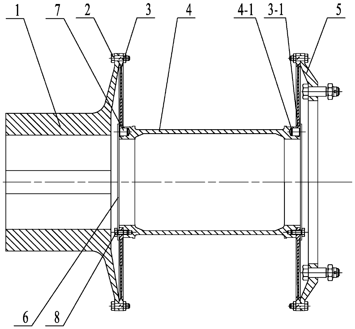
[0010] Specific implementation mode one: combine Figure 1 to Figure 2 Describe this embodiment. A diaphragm coupling for connecting a BPRT transmission clutch in this embodiment includes an input flange 1, an intermediate shaft 4, an output flange 5, and two diaphragms 3. The shape of the intermediate shaft 4 is It is a hollow shell with both ends open. A diaphragm 3 is provided at both ends of the intermediate shaft 4 respectively. The diaphragm 3 and the intermediate shaft 4 are positioned by a plurality of positioning pins 7. The middle part of the outer end of the diaphragm 3 is provided with a There is a positioning plate 6, and the outer end surface of the positioning plate 6 is evenly distributed with a plurality of connecting bolts 8 along the circumferential direction. The ends of the connecting bolts 8 pass through the diaphragm 3 and are screwed on the end surface of the intermediate shaft 4. The flanges of the flange 5 are fixedly connected to the outer circumfere...

specific Embodiment approach 2

[0012] Specific implementation mode two: combination figure 1 To describe this embodiment, the input flange 1 , the membrane disc 3 , the intermediate shaft 4 and the positioning plate 6 described in this embodiment are all arranged coaxially. The undisclosed technical features in this embodiment are the same as those in the first embodiment.

specific Embodiment approach 3

[0013] Specific implementation mode three: combination figure 1 To illustrate this embodiment, a plurality of pin holes 4-1 are evenly arranged on both end surfaces of the intermediate shaft 4 in this embodiment along the circumferential direction, and each pin hole 4-1 is respectively inserted with a positioning pin 7 A plurality of pin holes 3-1 are evenly distributed along the circumferential direction on the end surface of the membrane disc 3, and the pin holes 3-1 are set on the outside of the positioning pin 7, and the positioning pin 7 is arranged on the inside of the positioning plate 6. The undisclosed technical features in this embodiment are the same as those in the first or second specific embodiment.


PUM


Abstract

The invention relates to a diaphragm disc coupling for connecting a BPRT speed changing clutch, and relates to the technical field of mechanical transmission. The diaphragm disc coupling aims to solvethe problems that the axial size of an existing diaphragm disc coupling is large, the mass is large, consequently the unit dynamic balance precision is low, and the unit operation stability is affected. The diaphragm disc coupling comprises an input flange, an intermediate shaft, an output flange and two diaphragm discs, the shape of the intermediate shaft is a hollow shell with openings in the two ends, the two ends of the intermediate shaft are each provided with one diaphragm disc, the diaphragm discs and the intermediate shaft are positioned through a plurality of positioning pins, the middle portions of the outer side ends of the diaphragm discs are provided with positioning plates, the end surfaces of the outer sides of the positioning plates are uniformly provided with a pluralityof connecting bolts in the circumferential direction, the tail ends of the connecting bolts penetrate through the diaphragm discs, the connecting bolts rotate on the end face of the intermediate shaft, and flange plates of the input flange and the output flange are fixedly connected to the outer circumference of the outer side end of one diaphragm disc through the multiple connecting bolts. The diaphragm disc coupling is used for connecting the BPRT speed changing clutch.

Description

technical field [0001] The invention relates to the technical field of mechanical transmission, in particular to a diaphragm coupling for connecting a BPRT transmission clutch. Background technique [0002] The BPRT unit is a complete set of blast furnace blast energy recovery unit driven by the gas turbine and the motor coaxially. By installing the BPRT unit, it can not only recover the pressure energy and heat energy of the blast furnace top gas, reduce the flow noise of the gas transmission pipeline network, but also Highly intelligent control of blast furnace top pressure, axial fans, and gas turbines improves the smelting intensity and output of blast furnaces. The variable speed clutch is the core equipment in the BPRT unit, and it is connected with the gas turbine and the blower through a coupling. The traditional unit adopts diaphragm coupling, which has the advantages of low manufacturing cost and reliable operation. With the continuous improvement of the power an...

Claims


Application Information

Patent Timeline
Patent Type & Authority Applications(China)
IPC IPC(8): F16D3/56
CPCF16D3/56
Inventor 李硕曹安港宗浩刘欣欣邢立峰宋铎刘拥军陈妍闵颜峰强科边山城杨彩绒刘海军周向民
Owner HARBIN GUANGHAN POWER TRANSMISSION
Why Eureka
Try Eureka