
A phosphogypsum calciner

A calcination furnace and phosphogypsum technology, which is applied in the field of phosphogypsum calcination, can solve the problems of enlarged diameter of flame-breathing furnace, impossibility of direct application, environmental pollution of phosphogypsum, etc., and achieve the effect of smooth movement, reduced impact and uniform heating

Active Publication Date: 2021-08-06
ZHENGZHOU SUNDY BUILDING TECH
View PDF4 Cites 0 Cited by
  • Summary
  • Abstract
  • Description
  • Claims
  • Application Information

AI Technical Summary

Problems solved by technology

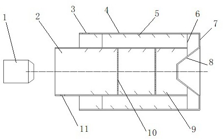
[0002] Phosphogypsum is a by-product produced by phosphorus chemical enterprises. Due to its high water content, harmful substances and acid ions, and the main component is dihydrate gypsum, it cannot be directly applied to building construction and other occasions where gypsum is used, causing a large amount of accumulation , so as to cause new environmental pollution; for this reason, the inventor first invented phosphogypsum to remove harmful substances and acid ions through calcination, so that it can be converted into a complex phase hemihydrate gypsum mixture that can be used for building construction, and solve the problem of phosphorus A large amount of gypsum accumulation causes environmental pollution, and at the same time, it provides high-strength and water-resistant gypsum building materials for construction; at present, the calciner used is a rotary kiln-type double-barrel calciner, and the backfire calciner is used. The method is to feed the material at the end of the outer cylinder of the calciner located at the flame-injection furnace. With the rotation of the drum, under the action of the pusher plate, the gypsum powder moves from one end of the flame-injection furnace to the other end, and then moves to the end of the outer cylinder. After entering the inner cylinder through the cone, the gypsum powder moves from the far end of the inner cylinder to the near end of the flame-throwing furnace, and the flame-throwing furnace needs strong wind assistance when spraying fire, so that the heat of the flame can be sprayed to the deep part of the inner cylinder. To achieve the purpose of calcining gypsum; due to the requirements for the flame length of the flame-throwing furnace, the nozzle diameter of the flame-throwing furnace is limited, that is to say, the diameter of the flame-throwing furnace cannot be infinitely enlarged, and the diameter of the inner cylinder is not different from the flame-throwing diameter of the flame-throwing furnace. When it is large, the fire sprayed by the flame-breathing furnace can take into account the overall wind of the inner cylinder section, and at the same time, there is no need to increase the wind pressure of the flame-breathing furnace; It cannot be expanded infinitely, because the flame-breathing effect cannot be formed if the diameter of the flame-breathing furnace exceeds the limit. In order to meet the large-diameter inner tube with large gypsum capacity and high output, it is necessary to increase the fire-breathing wind. Because the mouth of the flame-breathing furnace is small, The flame or hot air flow from the flame-injecting furnace is concentrated in the central area of ​​the inner cylinder section corresponding to the nozzle diameter of the flame-injecting furnace. Therefore, a hot air column will be formed in the central area of ​​the inner cylinder section. Particles, the hot air column can blow these fine particles to the far end of the inner cylinder and then return to the outer cylinder, which cannot ensure smooth entry into the calcination area near the flame-breathing furnace, or stop advancing after entering the calcination area, resulting in over-burning and scrapping. The calcination quality and output of phosphogypsum have a great impact, the result is no material or less material, or the material is burned to death

Method used


Image

  • A phosphogypsum calciner
  • A phosphogypsum calciner
  • A phosphogypsum calciner

Examples


Embodiment 2

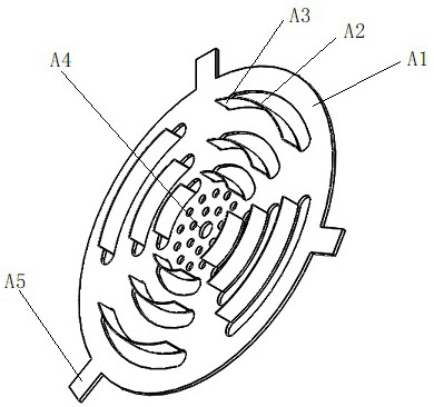
[0018] Embodiment 2, in this example, the same support member A1, the connecting frame as this example is selected as the connecting frame A5, and the central damping hole A4, which is the central damper hole A4 of this example. The long hole is the outer peripheral damper A2 in this example, and the inner side edge of the outer peripheral damped bore A2 is provided in the outer circumference of the supporting plate A3 toward the outer circumferential direction of the support body A1, which enables the bore from the outer peripheral The hot air flow flowing in A2 is directed to the inner wall direction of the inner cylinder 2; in combination of the calciner combination in accordance with the selection and mounting of the calcining furnace in the first embodiment, two the homoelectric device 10 of this example is selected, according to the example One position is mounted in the inner cylinder 2, ensuring that the air strip A3 is located in the tail direction of the inner cylinder 2...

Embodiment 3

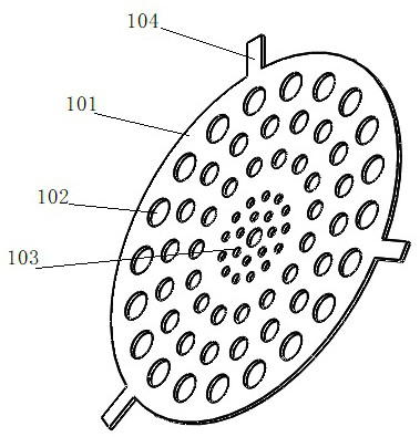
[0019] In this example, the main body of the calciner in this example is the same as that of the embodiment, and the difference is that the same connection frame B6 as in the same example is selected in this example, and a part of the ring is used. The outer circular support B1 is made of a steel sheet, an annular outer circle having a diameter of 1800 mm, an inner diameter diameter, a thickness of 5 mm; a large end diameter of the tapered support B2 is 1700 mm is 500 mm. , Height is 500 mm; a punching steel sheet having a thickness of 3 mm is wrapped and welded, and the punching diameter is 30 mm two-hole interval distance 50 mm cloth covered with a cone-shaped support B2 as a peripheral damped bore B3, and the thickness is selected A circular steel sheet having 5 mm diameter 500 mm is used as the central support B4, which is soldered with the small end of the tapered support B2; the diameter of the middle damping hole B5 is 20 mm, and the two-hole interval is 60 mm is covered wi...


PUM

PropertyMeasurementUnit
diameteraaaaaaaaaa
thicknessaaaaaaaaaa
thicknessaaaaaaaaaa

Abstract

A phosphogypsum calcining furnace, belonging to the field of phosphogypsum calcining, comprising a flame-throwing furnace, an inner cylinder, a feed port, an outer cylinder, an outer cylinder pushing plate, an inner and outer cylinder connecting piece, an outer cylinder tail end, a cone, and an inner cylinder pushing plate , a pressure equalizing device, and a discharge port; the flame-injecting furnace is a coal-injection furnace or a gas-injecting furnace, installed at the discharge port of the inner cylinder, and its fire direction is located at the discharge end of the inner cylinder; the inner cylinder is arranged on the outer The inside of the cylinder is coaxial with the outer cylinder, and its outer wall is fixedly connected with the outer cylinder through the inner and outer cylinder connectors; the feed inlet is arranged on the outer cylinder, located at one end of the flame-breathing furnace, and runs through the wall thickness of the outer cylinder; The air flow is balanced, the material to be calcined is heated evenly, and the movement of the material to be calcined tends to be smooth, which improves the production efficiency and calcination quality.

Description

Technical field [0001] The present invention belongs to the field of phosphate calcination, and in particular, the present invention relates to a phosphite calciner of a binocular rotary roller using a coal furnace or a gas injection furnace as a heating source. Background technique [0002] Phosphate is a by-product produced by phosphorus chemical enterprises. Due to high moisture content, harmful substances and acidic ions, and main components are dihydrates, therefore, it is not possible to directly apply to other plasters and other applied plasters, resulting in a large amount of accumulation Therefore, it has caused new environmental pollution; for this purpose, the inventors will invent the phosphite is invented to remove harmful substances and acidic ions inventive, so that the phosphorus can be used to solve the phosphorus. Gypsum has a large amount of environmental pollution, and it provides a high strength and water-resistant plaster building material for building const...

Claims


Application Information

Patent Timeline
Patent Type & Authority Patents(China)
IPC IPC(8): C04B11/26C04B11/028
CPCC04B11/028C04B11/26
Inventor 赵嘉珩赵建纲
Owner ZHENGZHOU SUNDY BUILDING TECH
Learn More