
Medium-frequency power supply energy-saving control roll welding equipment and welding method thereof

An intermediate frequency power supply and rolling welding technology, which is applied in the direction of resistance welding equipment, welding equipment, roller electrode welding, etc., can solve the problem of how to save energy in welding equipment, and achieve the effects of stable current, low surface temperature and energy saving

Pending Publication Date: 2019-07-12
JIANHUA CONSTR MATERIALS (CHINA) CO LTD
View PDF13 Cites 2 Cited by
  • Summary
  • Abstract
  • Description
  • Claims
  • Application Information

AI Technical Summary

Problems solved by technology

[0004] The technical problem solved by the present invention is: to solve the problem of how to save energy for the welding equipment when the roll welding machine welds the steel cage

Method used


Image

  • Medium-frequency power supply energy-saving control roll welding equipment and welding method thereof
  • Medium-frequency power supply energy-saving control roll welding equipment and welding method thereof
  • Medium-frequency power supply energy-saving control roll welding equipment and welding method thereof

Examples


Embodiment Construction

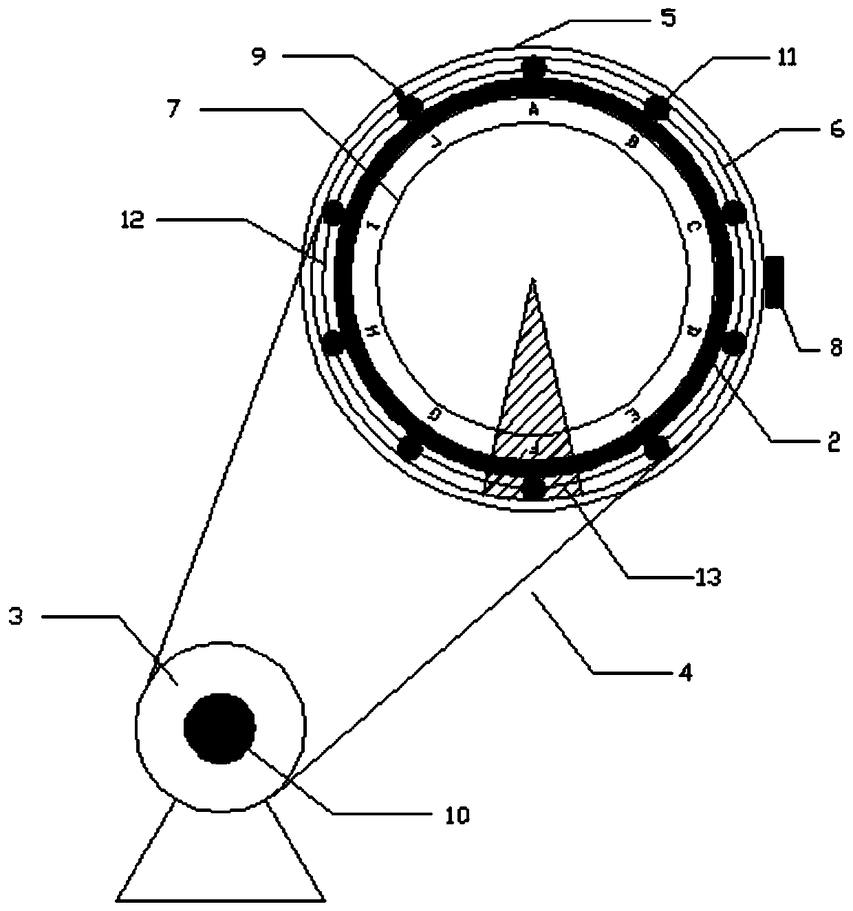
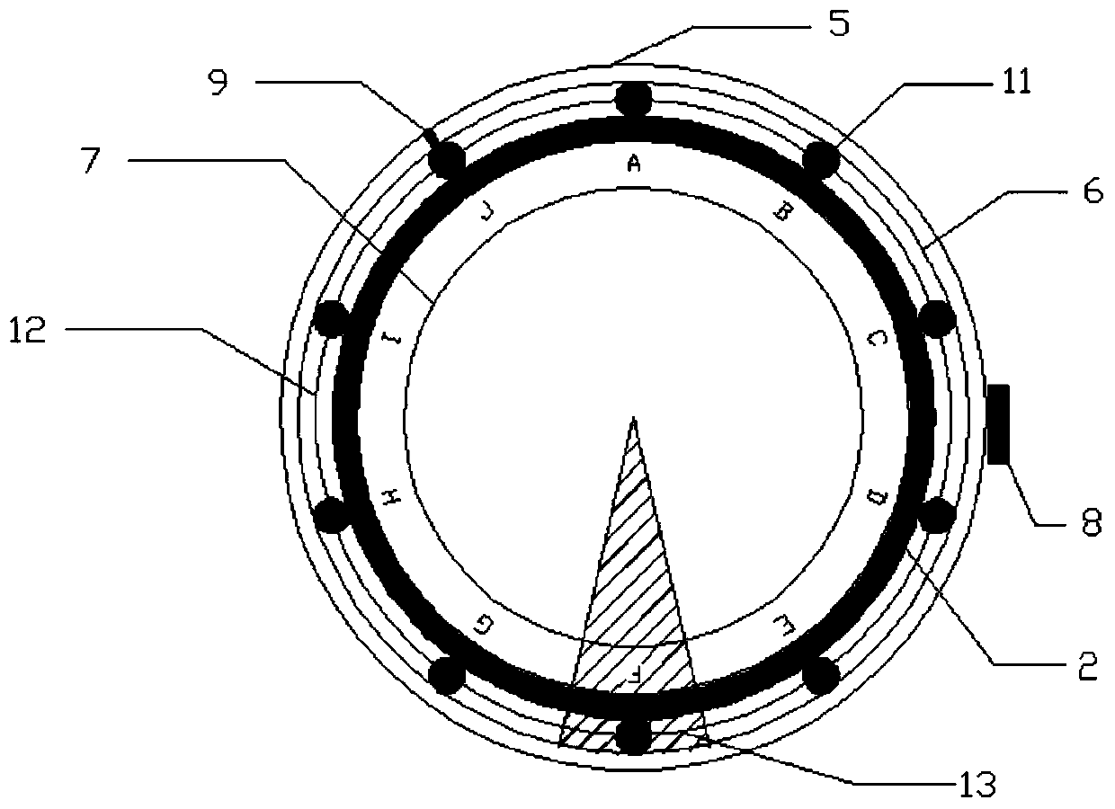
[0026] The preferred mechanism and motion realization method of the present invention will be further described below in conjunction with the accompanying drawings and specific embodiments.

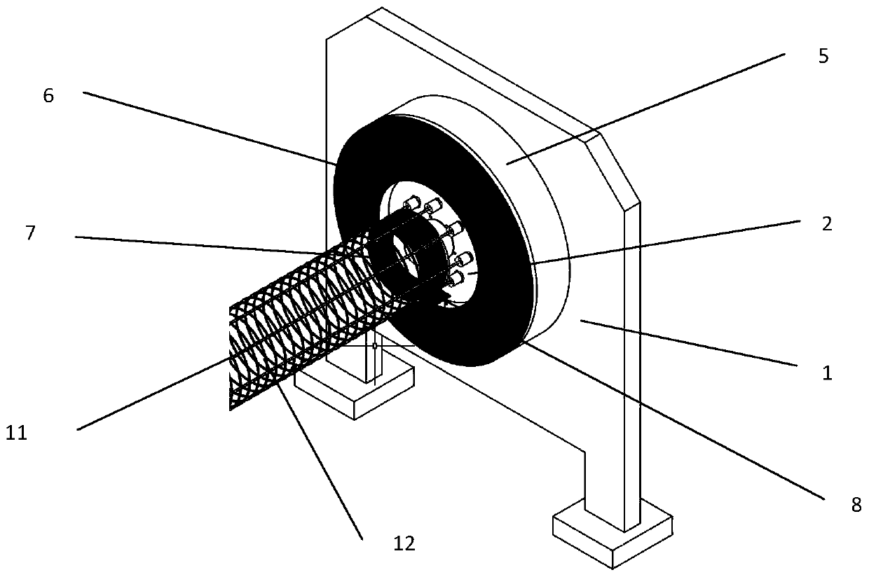
[0027] An intermediate frequency power supply energy-saving control roll welding equipment includes a calculation control system, an intermediate frequency DC power supply control system and an electromechanical system.

[0028] The operation control system of this embodiment is only described by taking the PLC control system as an example, but the operation control system may also be a single-chip microcomputer or other devices with similar functions.

[0029] The PLC control system has a high-speed data acquisition function. The interval allocation corresponding to the steel cage specification is set in the software program, and the pulse data collected by the rotary encoder 10 is collected in real time. Through calculation, the current position of the negative electrode 8 is judged, and...


PUM


Abstract

The invention provides medium-frequency power supply energy-saving control roll welding equipment and a welding method thereof. The equipment comprises a support, a fixed shaft, a rotating shaft, a rib penetrating disc and an annular positive electrode, wherein the rib penetrating disc and the fixed shaft are fixed to the support; the positive electrode is fixed relative to the rib penetrating disc and the fixed shaft; the fixed shaft, the rotating shaft, the rib penetrating disc, and the positive electrode are concentrically arranged from outside to inside; a negative electrode is fixedly arranged on the rotating shaft, a steel bar cage is arranged on the rib penetrating disc, and discharging sections are arranged at junctions of a main rib and auxiliary ribs; only when the negative electrode is rotated to the discharging sections, discharging occurs between the positive electrode and the negative electrode; and the positive electrode and the negative electrode stop discharging amongsections except the discharging sections. The welding method comprises the following steps that a plurality of discharging sections are arranged at the junctions of the main rib and the auxiliary ribsof the steel bar cage; only when the negative electrode is rotated to the discharging sections, discharging occurs between the positive electrode and the negative electrode; and the positive electrode and the negative electrode stop discharging among the sections except the discharging sections. According to the welding equipment and the welding method, the interval discharging sections of welding is calculated in an arithmetic control system through the collection of sensor signals according to the type of the steel bar cage actually produced, an automatic discharge welding function is realized, and therefore energy consumption is saved.

Description

technical field [0001] The invention mainly relates to the technical field of building construction machinery, in particular to an energy-saving welding control device and a welding method thereof. Background technique [0002] In the prefabricated component industry, the steel cage seam welding process is one of the important assembly processes, and the connection between the main reinforcement and the auxiliary reinforcement mostly adopts ordinary power frequency AC welding machines. From the perspective of welding type, there is room for energy-saving transformation. According to the sine wave current characteristics measured in ordinary power frequency welding, it can be seen intuitively that there are 2 zero-crossings in each sine wave waveform period, and the current obtained during this period is insufficient. In welding, it can only be consumed as heat energy, and the loss is serious (period 20ms), so there is a lot of energy wasted in the welding process. [0003] ...

Claims


Application Information

Patent Timeline
IPC IPC(8): B23K11/06B23K11/24B23K11/36
CPCB23K11/06B23K11/241B23K11/36
Inventor 陆杰米涛陈浩王金忠
Owner JIANHUA CONSTR MATERIALS (CHINA) CO LTD
Learn More