
Mower

A lawnmower and lawnmower technology, which is applied to harvesters, cutters, agricultural machinery and implements, etc., can solve the problem of inconvenient adjustment of the position of the mowing cutter head, and achieve the effect of changing the mowing angle

Active Publication Date: 2019-07-12
GUANGZHOU COAYU ROBOT CO LTD
View PDF7 Cites 0 Cited by
  • Summary
  • Abstract
  • Description
  • Claims
  • Application Information

AI Technical Summary

Problems solved by technology

[0004] The purpose of the present invention is to provide a lawnmower to solve the technical problem of inconvenient adjustment of the position of the mowing cutter head in the prior art

Method used


Image

  • Mower
  • Mower
  • Mower

Examples


Embodiment 1

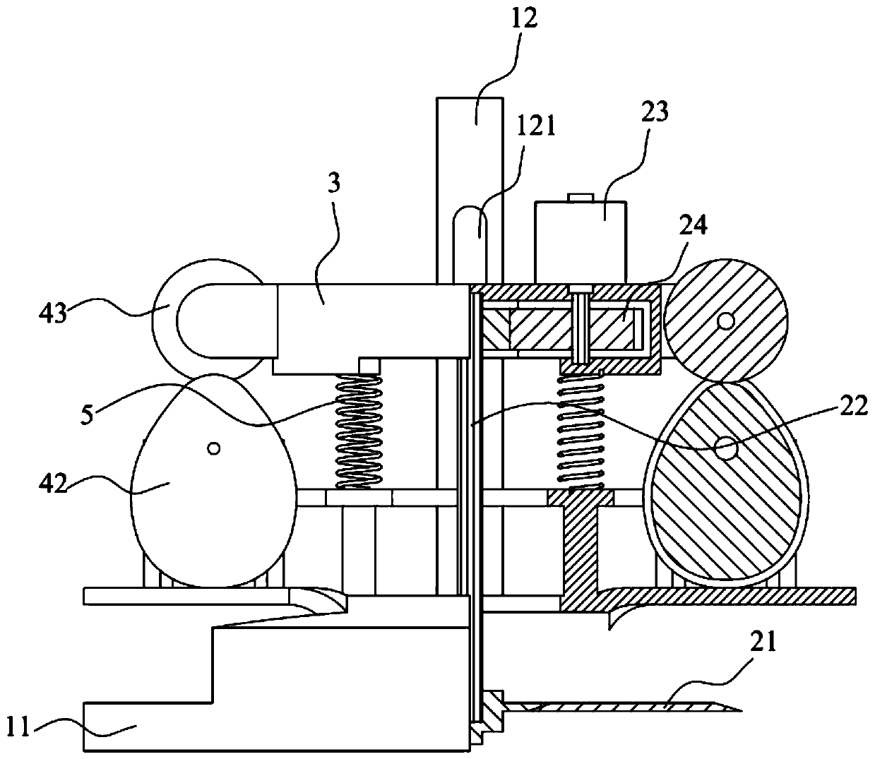
[0041] see Figure 1 to Figure 4 , the invention provides a lawn mower for mowing grass. The lawn mower comprises a main body of the machine, a support base 1 fixedly connected to the main body of the machine, and a mowing cutter head 21 arranged on the support base 1. The support base 1 includes a cover body 11 and a rod body 12 connected with the cover body 11, and the mowing knife The disk 21 is located in the cover body 11, and the cover body 11 plays a protective role to the mowing cutter head 21, and also prevents the operator from accidentally touching the mowing cutter head 21. The rod body 12 is arranged on the outer surface of the cover body 11 for connecting with other components. Mowing cutter head 21 is installed on the cutter shaft 22, and cutter shaft 22 is driven by motor 23, and motor 23 is connected with cutter shaft 22 by reduction mechanism 24, and motor 23 drives mowing cutter head 21 high-speed rotations to mow grass. In order to facilitate heat dissipa...

Embodiment 2

[0054] Figure 8 to Figure 10 Embodiment 2 is shown, in which components identical or corresponding to those in Embodiment 1 are identified with reference numerals corresponding to Embodiment 1. For simplicity, only the differences between Embodiment 2 and Embodiment 1 are described. The difference is that the transmission mechanism includes a gear 44 and a rack 45 , the gear 44 is connected to the driving part 41 , the rack 45 extends along the first direction, and the gimbal 3 is connected to the rack 45 in rotation. During the rotation process, the gear 44 can push the rack 45 to move, and the rack 45 drives the side of the gimbal 3 to change its position. The engagement of the gear 44 and the rack 45 has a locking effect, making the transmission more stable.

[0055] When the height of the mowing cutter head 21 needs to be adjusted, the two gears 44 are synchronously adjusted so that the two racks 45 are in the same position along the first direction, that is, the two ra...


PUM


Abstract

The invention discloses a mower and belongs to the technical field of forestry machinery. The mower comprises a body, a support fixedly connected to the body, and a mowing cutter arranged on the support, as well as a balance rack and two adjusting devices. The balance rack has a middle and two sides; the middle of the balance rack is rotationally connected with the support; the balance rack can move linearly in a first direction relative to the support; the mowing cutter is connected with the balance rack; the adjusting devices are fixed to the support; each side of the balance rack is provided with one adjusting device; the adjusting devices help adjust the relative positions of the two sides of the balance rack in the first direction; the balance rack can be driven to move and rock relative to the support. The support, the balance rack and the adjusting devices can cooperate to adjust the height and rocking angle of the mowing cutter, so that the mowing cutter can adapt to more applications.

Description

technical field [0001] The invention relates to the technical field of forestry machinery, in particular to a lawnmower. Background technique [0002] As a high-efficiency and long-lasting weeding method, mechanical mowing is widely used in the maintenance and replanting of green space gardening. A lawn mower generally includes a frame, an engine, a running gear and a mowing cutterhead, and the mowing cutterhead and the frame move with the running gear. The height of the position of the mowing cutter head determines the height of the mowing, and the grass higher than the mowing cutter head is cut off. [0003] In the currently used lawnmowers, the position of the mowing cutter head is mostly fixed during the mowing process. When encountering taller weeds, the mowing current will increase. If this happens for a long time, it will affect the battery life; at the same time, when encountering some relatively harsh weeds, there will be some working blind spots, which will affec...

Claims


Application Information

Patent Timeline
Patent Type & Authority Applications(China)
IPC IPC(8): A01D34/412
CPCA01D34/412
Inventor 李孟钦刘旭野王利鹏郑卓斌王立磊
Owner GUANGZHOU COAYU ROBOT CO LTD
Learn More