
High-power microwave spatial beam scanning planar array antenna

A planar array antenna and high-power microwave technology, which is applied to antennas, antenna arrays, and antenna arrays that are powered independently, can solve the problems of inability to realize platform conformal design, low antenna surface efficiency, and high cost

Active Publication Date: 2019-07-09
NAT UNIV OF DEFENSE TECH
View PDF4 Cites 4 Cited by
  • Summary
  • Abstract
  • Description
  • Claims
  • Application Information

AI Technical Summary

Problems solved by technology

Existing hyperbolic antennas radiated by horns after mode conversion can realize beam scanning through two rotation axes, but this antenna has low aperture efficiency and cannot achieve a conformal design with the platform; high-power microwave radial line helical The array antenna has a GW-level power capacity. By controlling the spatial azimuth angle of the conductor in the helical radiation unit through the control unit (generally a stepping motor), a certain range of spatial beam scanning can be realized. However, for an antenna with M×N radiation units In terms of the system, M×N number of control units are required to control the rotation of the conductor in the helical radiation unit, resulting in a complex servo system, and the high cost of manufacturing the antenna due to the large number of control units

Method used


Image

  • High-power microwave spatial beam scanning planar array antenna
  • High-power microwave spatial beam scanning planar array antenna
  • High-power microwave spatial beam scanning planar array antenna

Examples


Embodiment Construction

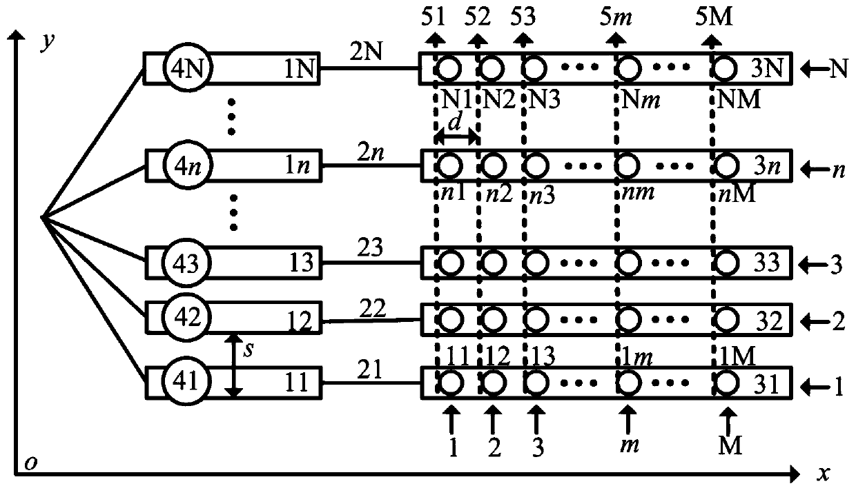
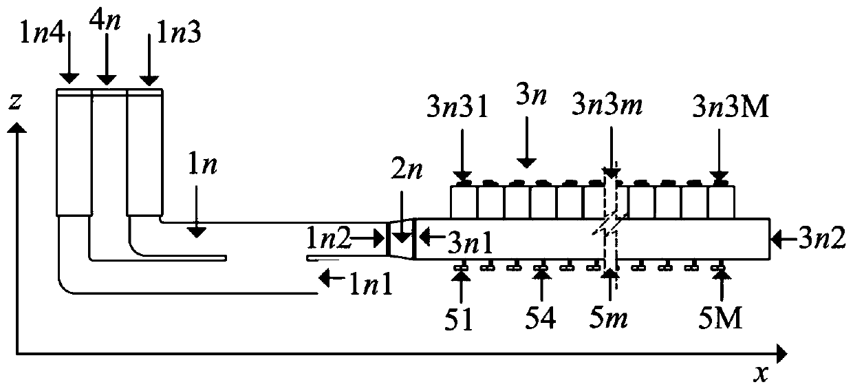
[0069] The structural diagram of the high-power microwave space beam sweepable planar array antenna system of the present invention is as follows figure 1 As shown, the present invention is made up of five parts, and they are respectively N (20figure 1 It is represented by a small circle, where 50figure 1 Indicated by a dotted line in , the conductor drive control unit in each helix controls the radiation unit in the corresponding column, that is, the conductor drive control unit 5m in the mth helix controls the radiation unit in the mth column). The nth rotary adjustable phase shifter 1n based on the rectangular waveguide narrow-side slot bridge and the nth high-power microwave one-dimensional beam sweepable linear array 3n are connected by the nth connecting waveguide 2n, and the three together form the nth along the x-axis direction line array. The structures of the N linear arrays are exactly the same, they are arranged in parallel along the y-axis in space to form a plana...


PUM


Abstract

The invention discloses a high-power microwave spatial beam scanning planar array antenna. The antenna is composed of N rotating adjustable phase shifters based on rectangular waveguide narrow-edge slot bridges, N connecting waveguides, N high-power microwave one-dimensional beam scanning linear arrays, N phase shifter phase control units, and driving control units of spiral inner conductors of Mlinear arrays. Each linear array has M radiation units. In the x-axis direction, the n1st to nMth radiation units constitute an nth row of radiation units. In the y-axis direction, the 1mth to Nmth radiation units constitute an mth column of radiation units. The mth spiral inner conductor driving control unit controls the mth column of radiation units. The nth phase shifter phase control unit adjusts the output phase of the nth rotating adjustable phase shifter based on a rectangular waveguide narrow-edge slot bridge. On the basis of realizing beam scanning, the antenna has high aperture efficiency and only needs M+N control motors.

Description

technical field [0001] The invention relates to an antenna in the technical field of high-power microwaves, in particular to a high-power microwave planar array antenna with space beam scanning capability. Background technique [0002] The high power microwave antenna is the terminal of the high power microwave system, and its performance has an important influence on the irradiation ability of the high power microwave system. With the development of high-power microwave technology, it is urgently required that the high-power microwave antenna has the ability of spatial beam scanning. Existing hyperbolic antennas radiated by horns after mode conversion can realize beam scanning through two rotation axes, but this antenna has low aperture efficiency and cannot achieve a conformal design with the platform; high-power microwave radial line helical The array antenna has a GW-level power capacity. By controlling the spatial azimuth angle of the conductor in the helical radiation...

Claims


Application Information

Patent Timeline
IPC IPC(8): H01Q1/36H01Q3/32H01Q21/06H01Q21/08
CPCH01Q1/36H01Q3/32H01Q21/061H01Q21/08
Inventor 袁成卫余龙舟张强孙云飞郝冬青许亮
Owner NAT UNIV OF DEFENSE TECH
Learn More