
Method and device for testing secondary system disturbance voltage of extra high voltage substation

A technology of disturbance voltage and secondary system, which is applied in the field of electromagnetic compatibility of power system substations, can solve the problems of the normal operation of secondary equipment and the uneven distribution of transient ground potential of the grounding grid, so as to achieve high reliability and safety and reduce damage to Influence of measurement, effect of reducing loop impedance

Active Publication Date: 2019-07-09
CHINA ELECTRIC POWER RES INST +2
View PDF6 Cites 2 Cited by
  • Summary
  • Abstract
  • Description
  • Claims
  • Application Information

AI Technical Summary

Problems solved by technology

[0002] The purpose of this invention is to solve the problem that the grounding network will appear transient when the lightning current flows through the grounding down conductor of lightning protection equipment such as lightning rods, lightning conductors or lightning arresters. The phenomenon of uneven ground potential distribution, this transient ground potential rise will be coupled to its core wire through the cable sheath and invade the secondary system, which may affect the normal operation of the secondary equipment. The disturbance voltage in the secondary system port caused by the state ground potential rise can evaluate the lightning protection capability of the secondary system, take effective measures to control and eliminate the threat to the secondary equipment, and meet people's requirements for system operation safety and power supply reliability Requirement, therefore, the present invention proposes a kind of UHV substation secondary system port disturbance voltage testing method

Method used


Image

  • Method and device for testing secondary system disturbance voltage of extra high voltage substation
  • Method and device for testing secondary system disturbance voltage of extra high voltage substation
  • Method and device for testing secondary system disturbance voltage of extra high voltage substation

Examples


Embodiment Construction

[0034] Exemplary embodiments of the present invention will now be described with reference to the accompanying drawings. However, the present invention can be implemented in many different forms and is not limited to the embodiments described herein. These embodiments are provided to disclose the present invention in detail and completely. Invention and fully convey the scope of the present invention to those skilled in the art. The terms in the exemplary embodiments shown in the drawings do not limit the present invention. In the drawings, the same units / elements use the same reference signs.

[0035] Unless otherwise specified, the terms (including scientific and technological terms) used herein have the usual meanings to those skilled in the art. In addition, it is understandable that the terms defined in commonly used dictionaries should be understood as having consistent meanings in the context of their related fields, and should not be understood as idealized or overly for...


PUM


Abstract

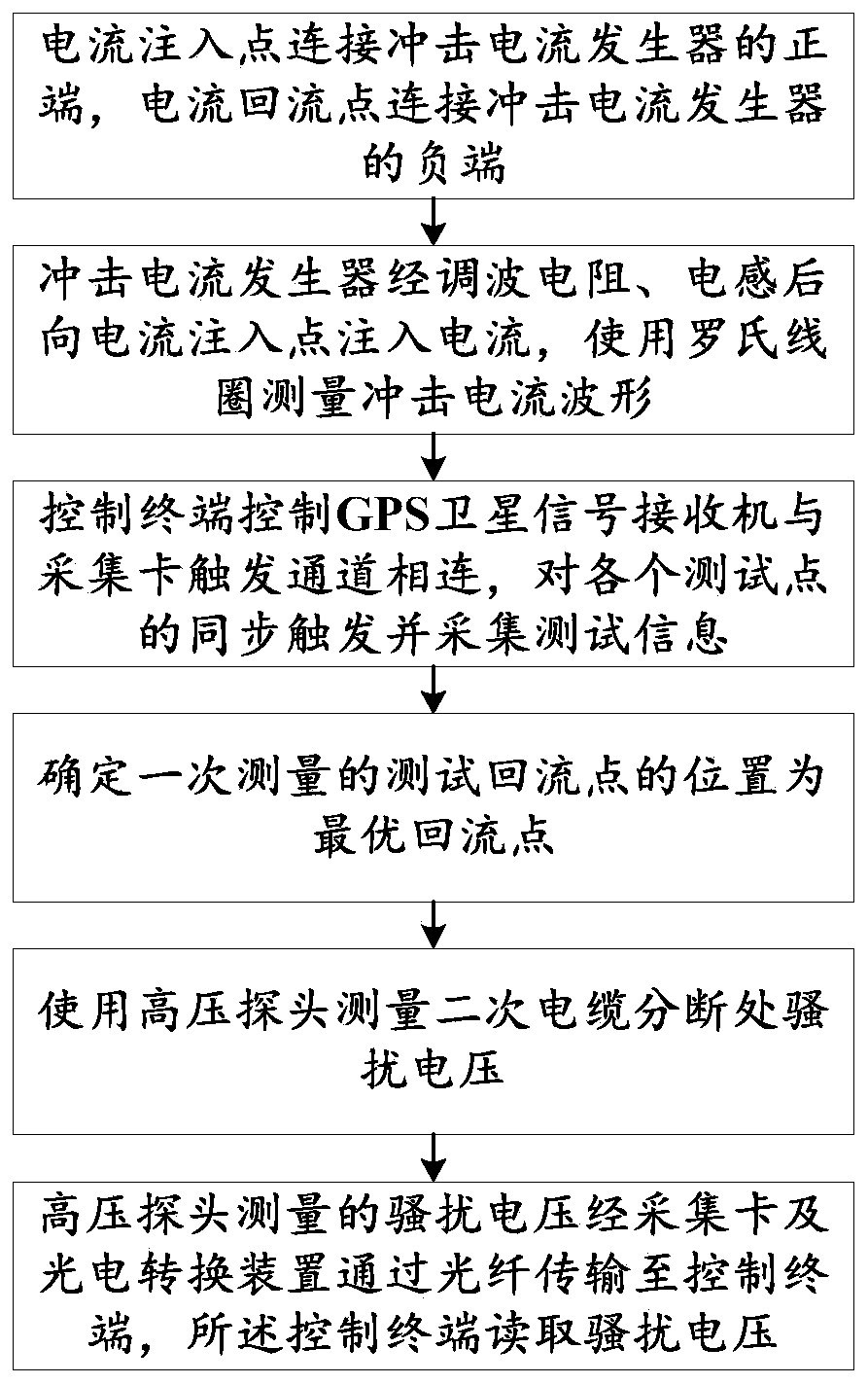
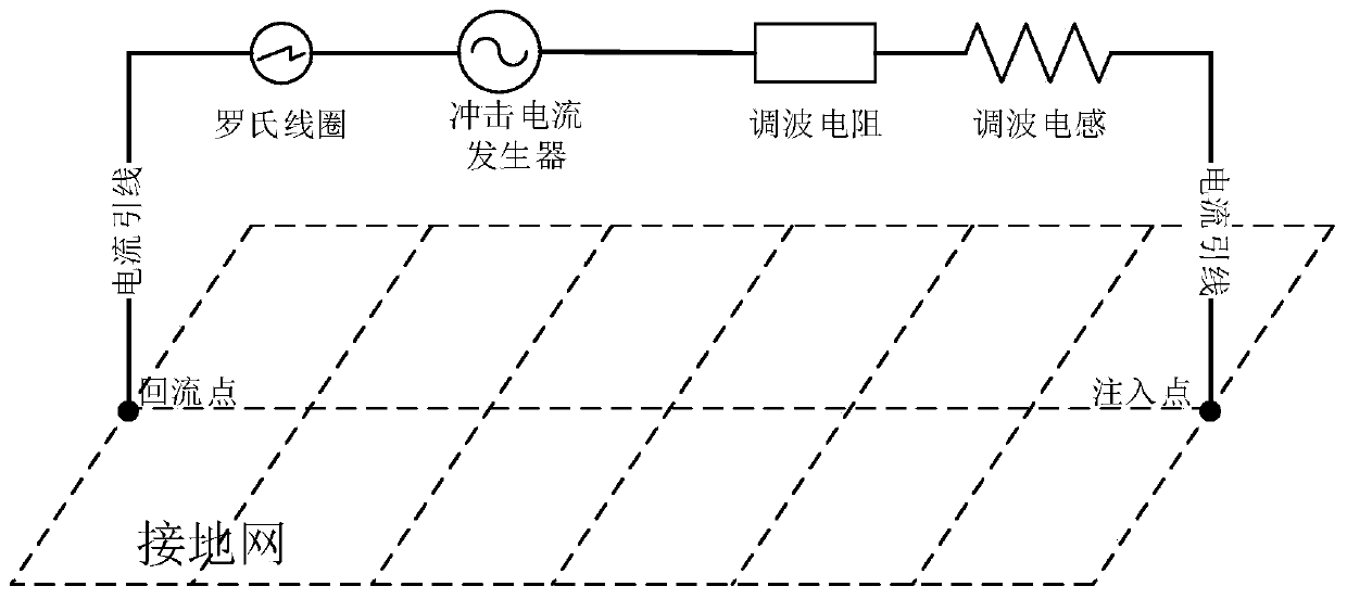
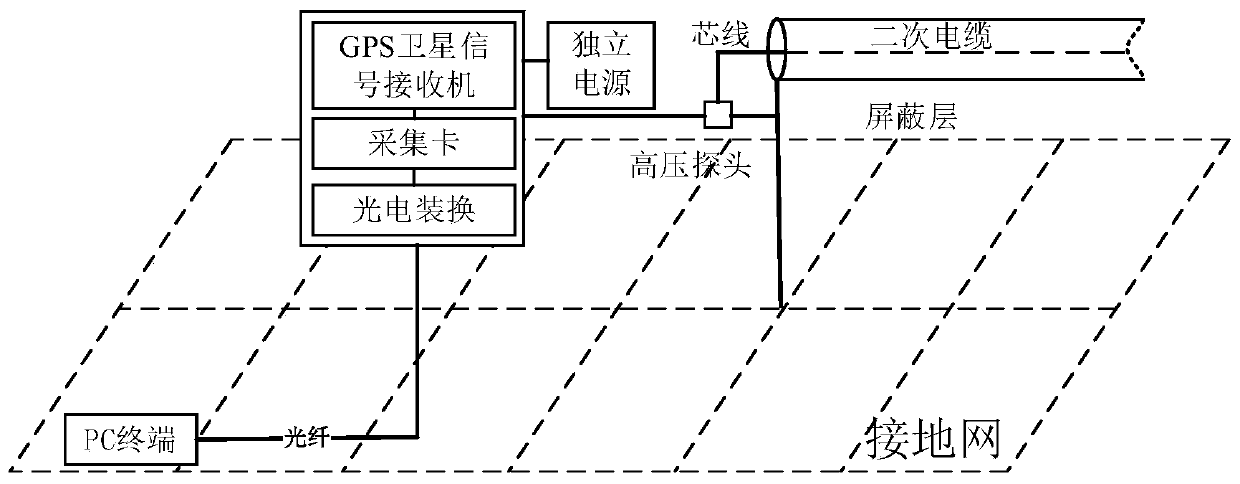
The invention discloses a method and device for testing a secondary system disturbance voltage of an extra high voltage substation and belongs to the field of power system substation electromagnetic compatibility. The method provided by the invention comprises the steps that a current injection point is connected with a positive end of an impulse current generator; a current backflow point is connected with a negative end of the impulse current generator; the impulse current generator passes a wave modulation resistor and a wave modulation inductor, then injects a current into the current injection point and measures a waveform of an impulse current; a control terminal controls a GPS satellite signal receiver to be connected with a collection card triggering channel, each test point is synchronously triggered and test information is collected; a position of a test backflow point of primary measurement is determined as the optimum backflow point; a disturbance voltage at a breaking partof a secondary cable is measured through utilization of a high voltage probe; the disturbance voltage measured by the high voltage probe passes a collection card and a photoelectric conversion deviceand is transmitted to the control terminal through utilization of a fiber, and the control terminal reads the disturbance voltage. According to the method and the device, workload of arranging lead wires when a test is carried out is reduced, and output amplitude of the impulse generator can be improved.

Description

Technical field [0001] The present invention relates to the field of electromagnetic compatibility of power system substations, and more specifically, to a method and device for testing the disturbance voltage of the secondary system of an ultra-high voltage substation. Background technique [0002] The purpose of the present invention is to aim at the phenomenon that when the lightning current flows through the ground down conductor of lightning protection equipment such as lightning rods, lightning conductors or lightning arresters, the grounding grid will show uneven distribution of transient ground potential, and this transient ground potential rises It will be coupled to its core wire through the cable sheath and invade the secondary system, which may affect the normal operation of the secondary equipment. Therefore, the only way to accurately test the disturbance voltage in the secondary system port caused by the transient ground potential rise of the grounding network. In ...

Claims


Application Information

Patent Timeline
Patent Type & Authority Applications(China)
IPC IPC(8): G01R19/165
CPCG01R19/16547
Inventor 张兆华时卫东康鹏张波刘卓然王森申巍贺子鸣沈海滨赵霞雷挺卢甜甜
Owner CHINA ELECTRIC POWER RES INST
Learn More