Experimental device and experimental method for establishing blast injury cell model

An experimental device and cell model technology, which is applied in the field of experimental devices for establishing impact injury cell models, can solve the problems of research and analysis of cell cascade reactions, high cost, large size, etc., and achieves low cost, simple production and convenient operation. Effect

Pending Publication Date: 2019-07-09
王春晖
View PDF3 Cites 0 Cited by
  • Summary
  • Abstract
  • Description
  • Claims
  • Application Information

AI Technical Summary

Problems solved by technology

TNT explosion source has the complexity and high risk of transportation, storage and detonation, and the experimental model has batch effect and poor repeatability; 2. Shock tube
The animal model of shock tube shock injury is relatively mature and widely used, but it also has the disadvantages of large size, complicated operation and high cost
However, the response of the body after shock injury is a very complex pathophysiological process, and various factors can affect the occurrence and development of the injury. At this time, it is impossible to accurately simulate the damage caused by the shock wave to the body by using the shock tube shock injury animal model. To study and analyze the cascade reaction between cells and reveal the pathophysiological changes of tissue cells after impact injury, so it is necessary to study and explore the injury mechanism of impact injury from the molecular level
However, there is currently no experimental device specially used to establish a cell model of blast injury. In order to better study the mechanism and pathophysiological changes of blast injury and provide a reliable basis for the treatment of blast injury, a standard, accurate, and controllable model should be established. The impact injury cell model is of great significance

Method used


Image

  • Experimental device and experimental method for establishing blast injury cell model
  • Experimental device and experimental method for establishing blast injury cell model
  • Experimental device and experimental method for establishing blast injury cell model

Examples


Embodiment Construction

[0024] The present invention will be further described below in conjunction with accompanying drawings and examples.

[0025] In describing the present invention, it is to be understood that the terms "central", "longitudinal", "transverse", "front", "rear", "left", "right", "vertical", "horizontal", The orientations or positional relationships indicated by "top", "bottom", "inner", "outer", etc. are based on the orientations or positional relationships shown in the drawings, and are only for the convenience of describing the present invention and simplifying the description, rather than indicating or implying The devices or elements referred to must have a specific orientation, be constructed and operate in a specific orientation, and therefore should not be construed as limiting the scope of the invention.

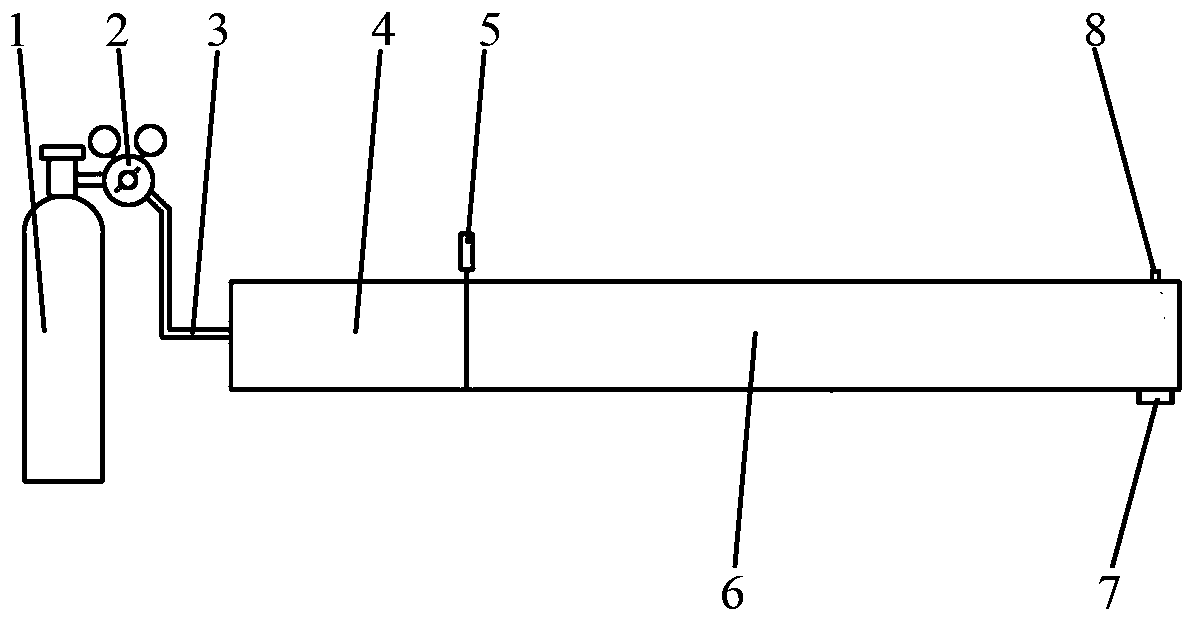
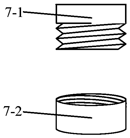
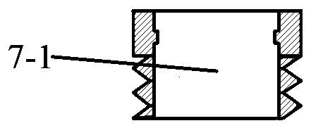
[0026] Such as Figure 1-3 As shown, an experimental device for establishing a shock injury cell model, including a high-pressure gas cylinder 1, a pressure reducing va...


PUM

PropertyMeasurementUnit
lengthaaaaaaaaaa
lengthaaaaaaaaaa

Abstract

The invention relates to an experimental device and an experimental method for establishing a blast injury cell model. The experimental device comprises a high-pressure gas cylinder, a pressure reducing valve, a connecting pipe, a driving section, an electromagnetic valve, a driven section, a pressure sensor and a cell culture dish bracket, and the high-pressure gas cylinder, the pressure reducingvalve, the connecting pipe, the driving section, the electromagnetic valve, the driven section, the pressure sensor and the cell culture dish bracket are connected in sequence, wherein the cell culture dish bracket comprises an external thread interface and an internal thread cap, and an annular bulge is arranged in the external thread interface. The invention also discloses an experimental method of the experimental device. Compared with the prior art, the experimental device is simple to manufacture, safe and stable, and can accurately control the pressure ratio between the driving sectionand the driven section by using the electromagnetic valve to form stable and repeatable shock waves, so that an accurate, controllable and repeatable blast injury cell model can be established.

Description

technical field [0001] The invention relates to the technical field of cell model construction, in particular to an experimental device and an experimental method for establishing a blast injury cell model. Background technique [0002] Blast injury is the damage to the body, especially air-containing organs such as the lungs, hearing apparatus, and gastrointestinal tract, caused by the overpressure and negative pressure of the shock wave. With the outbreak of local modern wars, frequent terrorist activities and serious unexpected industrial accidents, the research on the injury mechanism and treatment technology of impact injuries has attracted more and more attention. Establishing a scientific and accurate model is an important experimental method and means to realize impact injury research. At present, scholars at home and abroad have designed and developed a variety of impact injury animal models, which are mainly divided into the following two categories according to th...

Claims


Application Information

Patent Timeline
Patent Type & Authority Applications(China)
IPC IPC(8): G01N33/483
CPCG01N33/4833
Inventor 王春晖王梦琳王越林胡宏康唐渊
Owner 王春晖
Why Eureka
Try Eureka