A lining structure suitable for tunnels crossing active faults and its construction method

A technology for active faults and tunnels, applied in tunnel linings, tunnels, shaft linings, etc., can solve the problems of affecting the self-weight of lining structures, increasing rigidity, and small applicability, so as to facilitate rapid clearance, strengthen integrity and stability, The effect of shifting energy is good

Active Publication Date: 2020-07-31
SHANDONG UNIV
View PDF6 Cites 0 Cited by
  • Summary
  • Abstract
  • Description
  • Claims
  • Application Information

AI Technical Summary

Problems solved by technology

However, increasing the stiffness will affect the self-weight of the lining structure, which has higher requirements on the bearing capacity of the surrounding rock and economy, and has less applicability

Method used


Image

  • A lining structure suitable for tunnels crossing active faults and its construction method
  • A lining structure suitable for tunnels crossing active faults and its construction method
  • A lining structure suitable for tunnels crossing active faults and its construction method

Examples


Embodiment 1

[0033] This embodiment provides a lining structure suitable for tunnels crossing active faults, and optimizes the tunnel lining structure during tunnel construction to reduce earthquake damage to the tunnel.

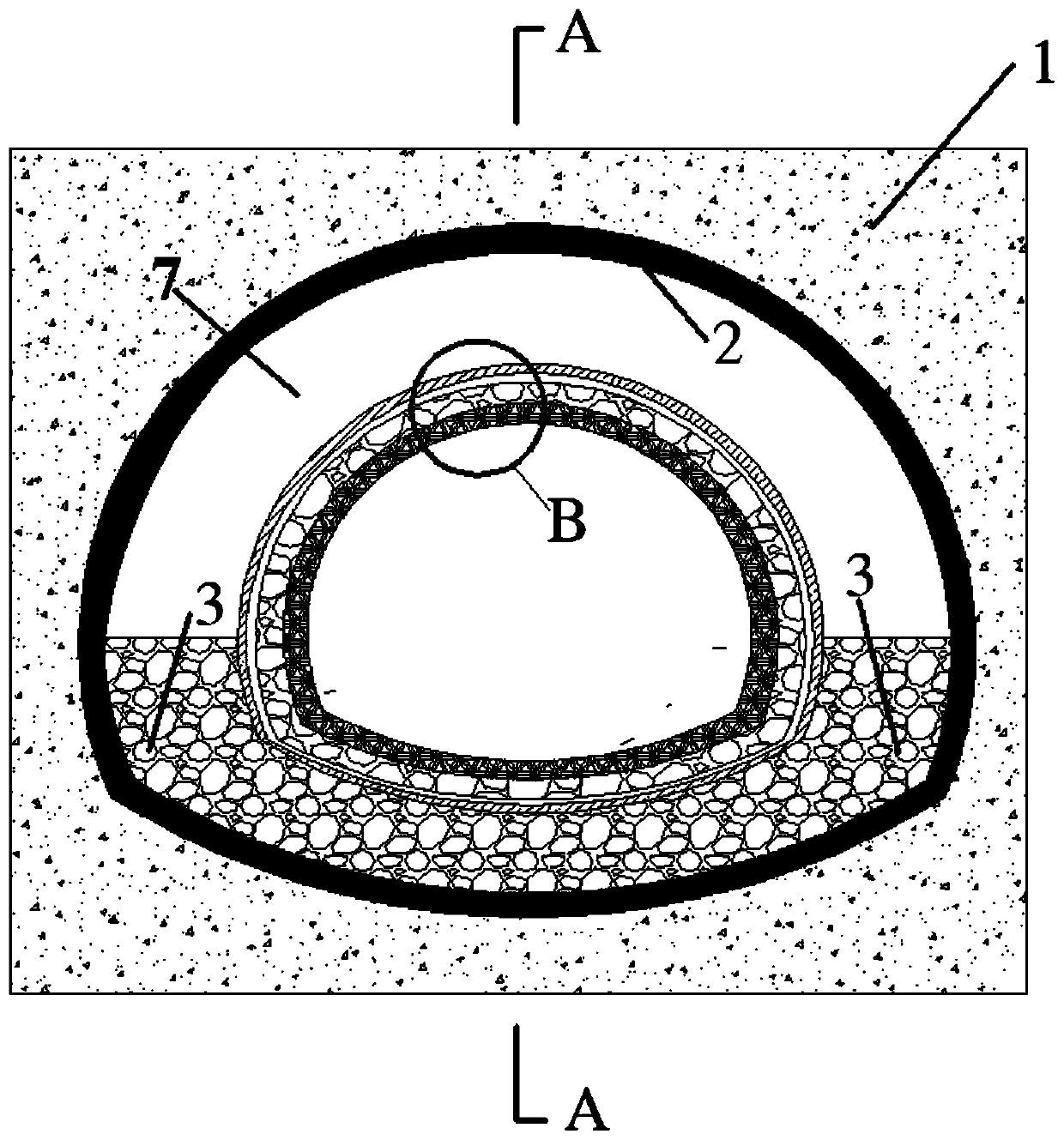
[0034] Please refer to the attached figure 1 with 2 , the lining structure suitable for tunnels crossing active faults proposed in this implementation includes a grouting reinforcement layer 2 and a tunnel support structure, the grouting reinforcement layer 2 is arranged on the excavation surface of the tunnel surrounding rock 1, and the tunnel support structure Set on the inner side of the grouting reinforcement layer 2, a clearance deformation layer 7 is reserved between the grouting reinforcement layer 2 at the upper part of the tunnel and the tunnel support structure, and a second An energy-dissipating and shock-absorbing layer 3 .

[0035] In this embodiment, the thickness of the clearance deformation layer 7 is 30-50 cm, and its function is: when the active fault...

Embodiment 2

[0046] This embodiment provides a construction method suitable for a lining structure of a tunnel crossing an active fault, and optimizes the tunnel lining structure during tunnel construction to reduce earthquake damage to the tunnel.

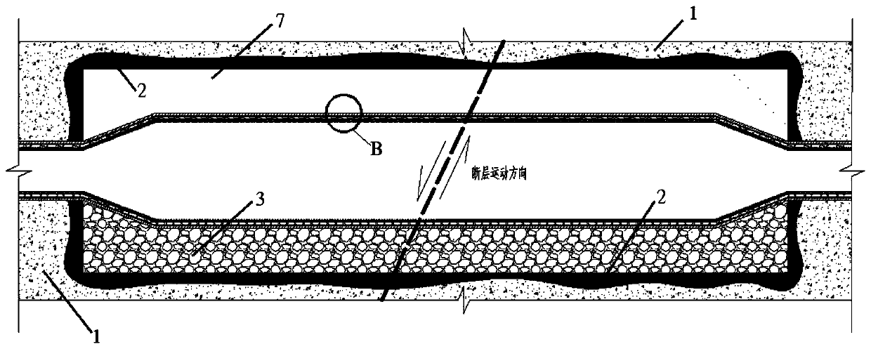
[0047] Please refer to the attached figure 1 , the construction method suitable for the lining structure of the tunnel crossing the active fault comprises the following steps:

[0048] S101, within the range of 50-100m near the active fault fracture zone, gradually increase the excavation surface area, reserve a clearance deformation layer between the excavation surface of the tunnel surrounding rock and the upper part of the tunnel, and reserve a clearance deformation layer between the excavation surface and the bottom of the tunnel Apply the first energy-dissipating shock-absorbing layer.

[0049] S102, the cross-sectional area of ​​the tunnel at the fault fracture zone is greater than that at the stable section.

[0050] S103, when passin...


PUM


Abstract

The invention discloses a lining structure optimization design method and system suitable for a tunnel crossing an active fault. The displacement inside the tunnel when a structural earthquake is caused by the dislocation of the active fault can be reduced, the inside of the tunnel dislocates but isn't interrupted after the earthquake, and the overall structural safety is maintained. The lining structure comprises a grouting reinforcement layer and a tunnel supporting structure which are arranged on a tunnel surrounding rock excavation face. The tunnel supporting structure is arranged on the inner side of the grouting reinforcement layer, a clearance deformation layer is reserved between the grouting reinforcement layer on the upper portion of the tunnel and the tunnel supporting structure, and a first energy dissipation and shock absorption layer is arranged between the grouting reinforcement layer on the lower portion of the tunnel and the tunnel supporting structure. The tunnel supporting structure is formed by compounding a tunnel primary support, a waterproof layer, a second energy dissipation and shock absorption layer and a tunnel secondary lining.

Description

technical field [0001] The present disclosure relates to the technical field of tunnel engineering, in particular to a lining structure suitable for a tunnel crossing an active fault and a construction method thereof. Background technique [0002] There are many active faults distributed in my country. Active faults are not only the main cause of tectonic earthquakes, but also cause the most serious damage along the fault line during earthquakes. Signs of active faults have been found in many cities in my country. Active faults will not only produce tectonic earthquakes, but the slow movement of active faults will also directly produce surface compression and dislocation deformation, directly threatening the safety of engineering facilities and urban construction. Therefore, when planning and designing large-scale projects such as super-tall buildings, large bridges, tunnels, expressways, and underground railways, it is necessary to pay close attention to the location and a...

Claims


Application Information

Patent Timeline
Patent Type & Authority Patents(China)
IPC IPC(8): E21D11/00E21D11/10E21D11/38E21D11/14E21D11/18
CPCE21D11/00E21D11/10E21D11/14E21D11/18E21D11/383
Inventor 薛翊国宋茜孔凡猛邱道宏公惠民李广坤
Owner SHANDONG UNIV
Why Eureka
Try Eureka