
Rail traffic vehicle auxiliary brake control system

A rail transit vehicle and auxiliary braking technology, applied in the field of rail transit vehicles, can solve the problems of increasing the loss along the pipeline, reducing the response speed of the system, and large area of ​​the airway board, so as to reduce the loss along the pipeline and reduce the Mounting brackets and mounting pipes, the effect of improving the response speed

Active Publication Date: 2019-07-09
KNORR BREMSE BRAKE EQUIP SUZHOU CO LTD
View PDF6 Cites 2 Cited by
  • Summary
  • Abstract
  • Description
  • Claims
  • Application Information

AI Technical Summary

Problems solved by technology

In the prior art, the design of the auxiliary brake control unit is unreasonable, and multiple control devices are scattered on the air circuit board, which requires a large area of ​​the air circuit board and is extremely inconvenient to install; and the purity of the air flow cannot be guaranteed
In addition, the auxiliary brake control unit and the EP2002 electro-pneumatic brake are arranged separately, and each needs to be installed with a bracket, which occupies a large space under the vehicle; the two need to be connected through an additional pipeline, which increases the loss along the pipeline and reduces the system responsiveness and increased cost

Method used

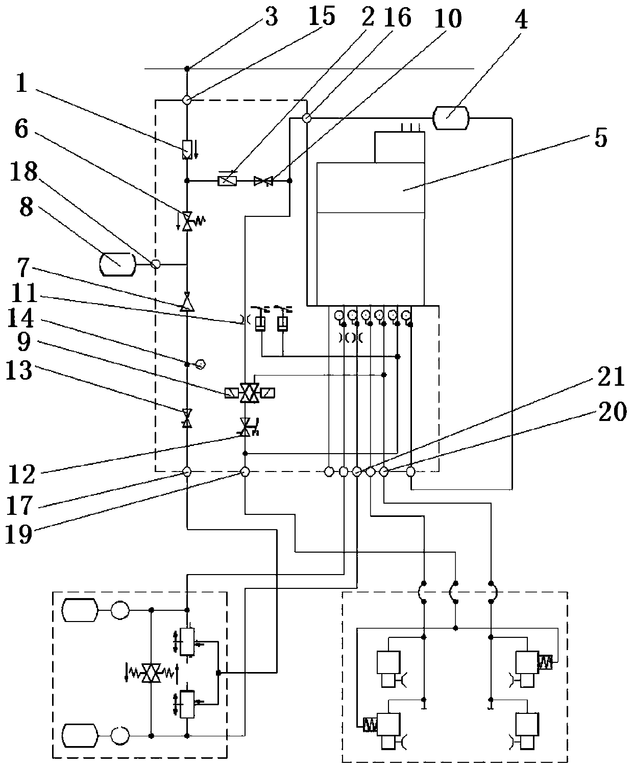
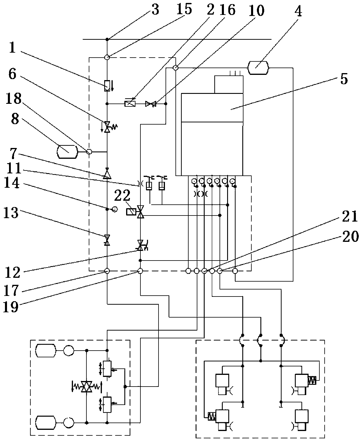
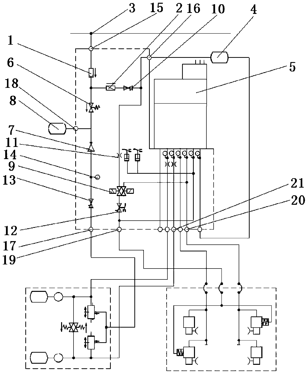

Image

  • Rail traffic vehicle auxiliary brake control system
  • Rail traffic vehicle auxiliary brake control system
  • Rail traffic vehicle auxiliary brake control system

Examples


Embodiment Construction

[0021] In order to enable those skilled in the art to better understand the solutions of the present invention, the following will clearly and completely describe the technical solutions in the embodiments of the present invention in conjunction with the drawings in the embodiments of the present invention. Obviously, the described embodiments are only It is an embodiment of a part of the present invention, but not all embodiments. Based on the embodiments of the present invention, all other embodiments obtained by persons of ordinary skill in the art without making creative efforts shall fall within the protection scope of the present invention.

[0022] It should be noted that the terms "first" and "second" in the description and claims of the present invention and the above drawings are used to distinguish similar objects, but not necessarily used to describe a specific sequence or sequence. It is to be understood that the data so used are interchangeable under appropriate ...


PUM


Abstract

The invention discloses a rail traffic vehicle auxiliary brake control system which comprises a filter arranged on a pipeline and communicated with a main air pipe, a check valve communicated with thefilter, and a plurality of connecting ports. The main air pipe is communicated with the auxiliary brake control system. The check valve is communicated with a brake air storage cylinder. The auxiliary brake control system further comprises an overflow valve communicated with the filter, a depressurizing valve communicated with the overflow valve. a third plug communicated with the check valve, athrottling valve communicated with the third plug, a controllable valve communicated with the throttling valve, and a second plug communicated with the controllable valve. The depressurizing valve iscommunicated with an air spring system. The overflow valve is communicated with an air spring air storage cylinder. The second plug is connected with a parking brake unit. The auxiliary brake controlsystem integrates the air filtering and supplying functions of the brake air storage cylinder and the air supply and vehicle parking brake control functions of the air spring system; corresponding installing supports and installing pipelines can be reduced, the linear loss of the pipelines is reduced, and the response speed of the system is increased.

Description

technical field [0001] The invention relates to the field of rail transit vehicles, in particular to an auxiliary braking control system for rail transit vehicles. Background technique [0002] In the domestic urban rail transit braking field, EP2002 electro-pneumatic brakes occupy most of the market share, and as the provider of the installation bracket and auxiliary braking control function of EP2002 electro-pneumatic brakes, the auxiliary braking control unit is in The proportion of models equipped with EP2002 electro-pneumatic brakes is also higher than 50%. Therefore, the auxiliary braking control unit is widely used in the domestic urban rail transit industry. The auxiliary braking control system is an integrated device. All vehicles are installed. The auxiliary braking control unit in the prior art is unreasonably designed, and multiple control devices are scattered on the air circuit board, which requires a large area of ​​the air circuit board and is extremely inco...

Claims


Application Information

Patent Timeline
IPC IPC(8): B61H11/06
CPCB61H11/06
Inventor 陆凤祥沈斌
Owner KNORR BREMSE BRAKE EQUIP SUZHOU CO LTD
Learn More