Vehicle bumper device

A technology for bumpers and vehicles, applied in the directions of bumpers, vehicle parts, vehicle safety arrangements, etc., can solve the problems of easy reduction, easy deformation and load resistance, and achieve the effect of suppressing the reduction of load resistance.

Inactive Publication Date: 2019-07-09
HONDA MOTOR CO LTD
View PDF7 Cites 1 Cited by
  • Summary
  • Abstract
  • Description
  • Claims
  • Application Information

AI Technical Summary

Problems solved by technology

[0006] The inclined part of the bumper beam is formed in a curved shape, so when a collision load is input, there is a problem that the cross-sectional shape is easily deformed compared with the central part, and the load resistance is likely to be lowered

Method used


Image

  • Vehicle bumper device
  • Vehicle bumper device
  • Vehicle bumper device

Examples


Embodiment Construction

[0035] Hereinafter, a case where the present invention is applied to a rear bumper device of a vehicle will be described, but the present invention can also be applied to a front bumper device of a vehicle.

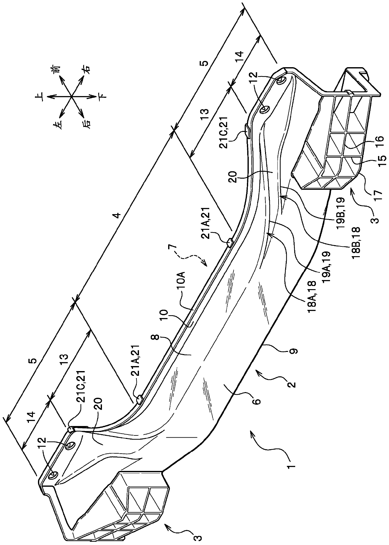
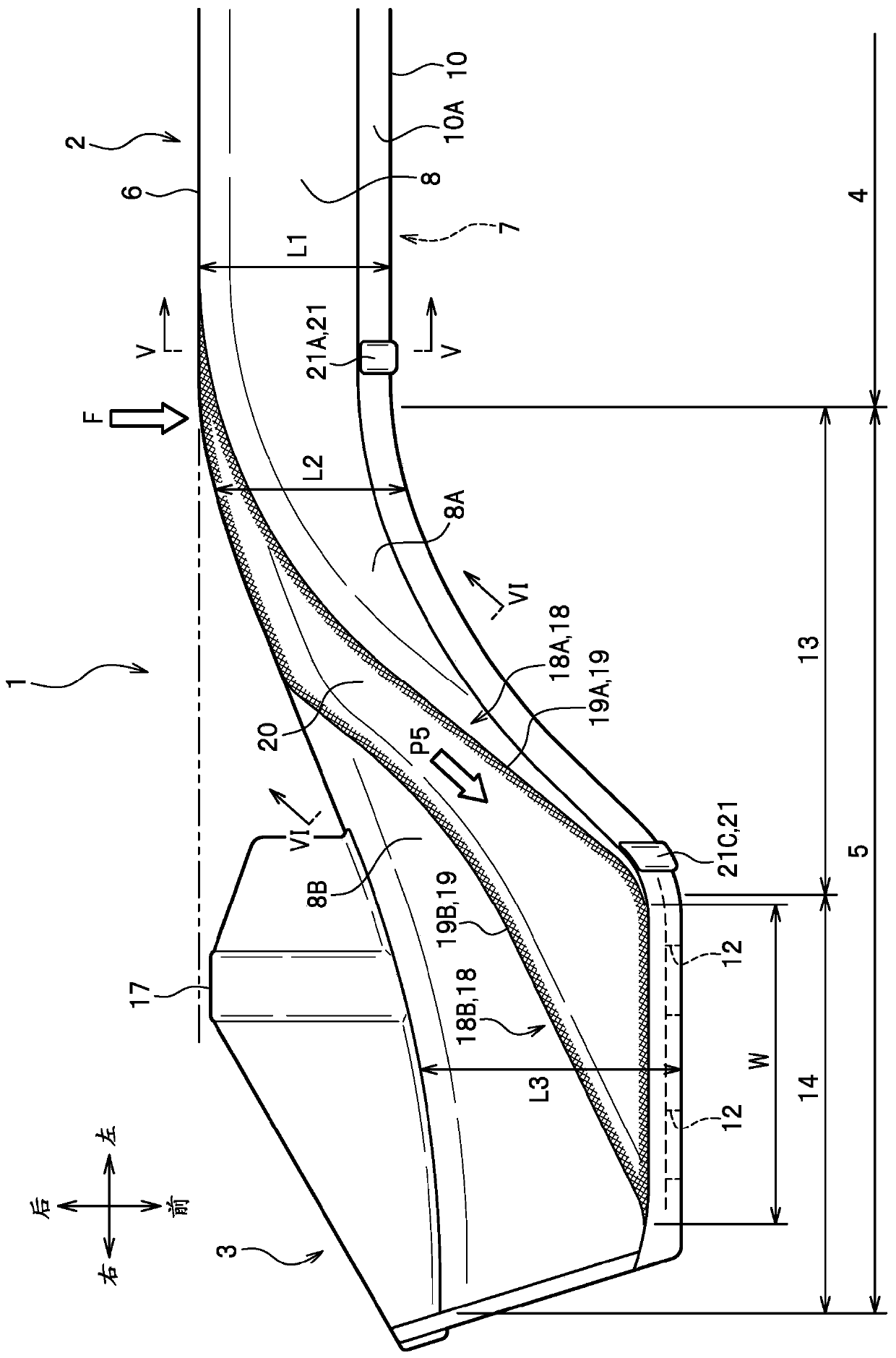
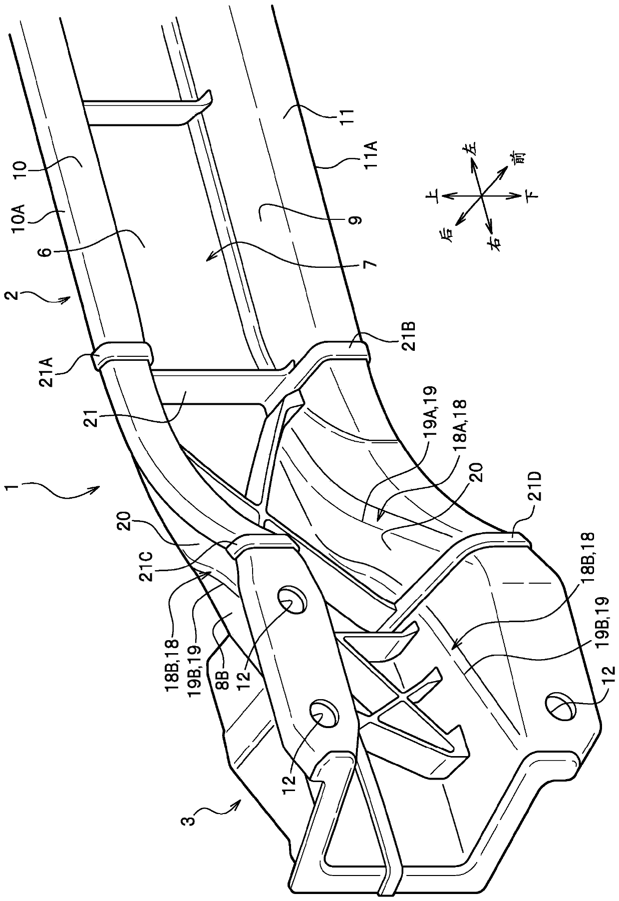
[0036] refer to Figure 1 to Figure 3 , the vehicle bumper device 1 is configured to include a bumper beam 2 and a bumper auxiliary portion 3 . The bumper beam 2 is formed of continuous fiber resin. The continuous fiber resin is, for example, thermoplastic CFRP (Carbon Fiber Reinforced Plastics: carbon fiber reinforced plastics). Such as Figure 4 As shown in (a), the continuous fiber resin includes a thermoplastic resin R arranged in a matrix and carbon fibers C1 composed of long fibers. The carbon fibers C1 are regularly oriented. On the other hand, the bumper auxiliary part 3, which will be described in detail later, is formed of short-fiber resin. Such as Figure 4 As shown in (b), the short fiber resin includes the thermoplastic resin R and the carbon fiber C2 ...


PUM


Abstract

A vehicle bumper device which can control deformation of a cross section of an inclined portion of a bumper beam and which can suppress reduction of load resistance of the bumper beam is provided. Thevehicle bumper device (1) includes: (i) a bumper beam (2) formed of continuous fiber resin and including a central portion (4) that extends in a vehicle width direction and a left-right pair of lateral portions (5) that respectively extend from opposite ends of the central portion and curve toward a vehicle body; and (ii) bumper auxiliary portions (3) formed of short fiber resin different from the continuous fiber resin and protruding respectively from the lateral portions (5) outward in a vehicle front-rear direction. The bumper beam has an approximately U-shaped cross section, and is provided with a collision load receiving section (6) that faces outward in the vehicle front-rear direction and a vehicle body attachment section (7) that has an opening oriented toward the vehicle body. The lateral portions (5) each have ridgelines (19) defined by a surface step (18) formed on the collision load receiving section and the vehicle body attachment section.

Description

technical field [0001] The present invention relates to a vehicle bumper device. Background technique [0002] Conventionally, there is known a vehicle bumper device arranged at the front end or rear end of a vehicle body, including a bumper beam made of continuous fiber resin, which has a central portion extending in the vehicle width direction and extending from both ends of the central portion toward the vehicle body. A pair of left and right inclined portions curved sideways; and a bumper auxiliary portion formed of short-fiber resin protruding outward in the front-rear direction from the inclined portions; (for example, refer to Patent Document 1). According to such a bumper device for a vehicle, by dividing the bumper beam into the continuous fiber resin and the bumper auxiliary part from the short fiber resin, it is possible to realize the impact energy absorption function, weight reduction, and cost reduction at the same time. [0003] prior art literature [0004]...

Claims


Application Information

Patent Timeline
Patent Type & Authority Applications(China)
IPC IPC(8): B60R19/02B60R19/03B60R19/18
CPCB60R19/02B60R19/03B60R19/18B60R2019/186B60R2019/1806B60R19/023B60R19/24
Inventor 弥武朋也
Owner HONDA MOTOR CO LTD
Why Eureka
Try Eureka