
Novel large-angle rotation horizontal band sawing machine

A large-angle, band sawing machine technology, applied in the field of sawing machines, can solve the problems of reducing the sawing flexibility of the sawing frame to the workpiece, affecting the positional flexibility of the workpiece clamping device, etc., achieving flexible angles and positions, and ingenious structural design , flexible rotation effect

Pending Publication Date: 2019-07-09
浙江锯力煌工业科技股份有限公司
View PDF0 Cites 4 Cited by
  • Summary
  • Abstract
  • Description
  • Claims
  • Application Information

AI Technical Summary

Problems solved by technology

[0002] The sawing machine is a machine tool that realizes continuous cutting in processing and production. Usually, the sawing machine is used to cut large workpieces. The working method is to let the saw blade touch the workpiece, and then pull the saw blade down. Due to the different cutting positions of the workpiece, there are When it is necessary to cut the workpiece at an angle, the traditional band sawing machine is installed on a cylindrical rod to move up and down. The cylindrical rod can rotate, and then add to the sawing frame to strengthen the sawing frame. The support rod with strong bending strength can rotate in the circular arc direction on the sawing machine, so that the workpiece can be sawed at an angle. Since the support rod will also block the workpiece placement, this method greatly reduces the saw The flexibility of the cutting frame body to the sawing of the workpiece, and some angles cannot be sawed, which will also affect the flexibility of the position of the workpiece clamping device

Method used


Image

  • Novel large-angle rotation horizontal band sawing machine
  • Novel large-angle rotation horizontal band sawing machine
  • Novel large-angle rotation horizontal band sawing machine

Examples


Embodiment 1

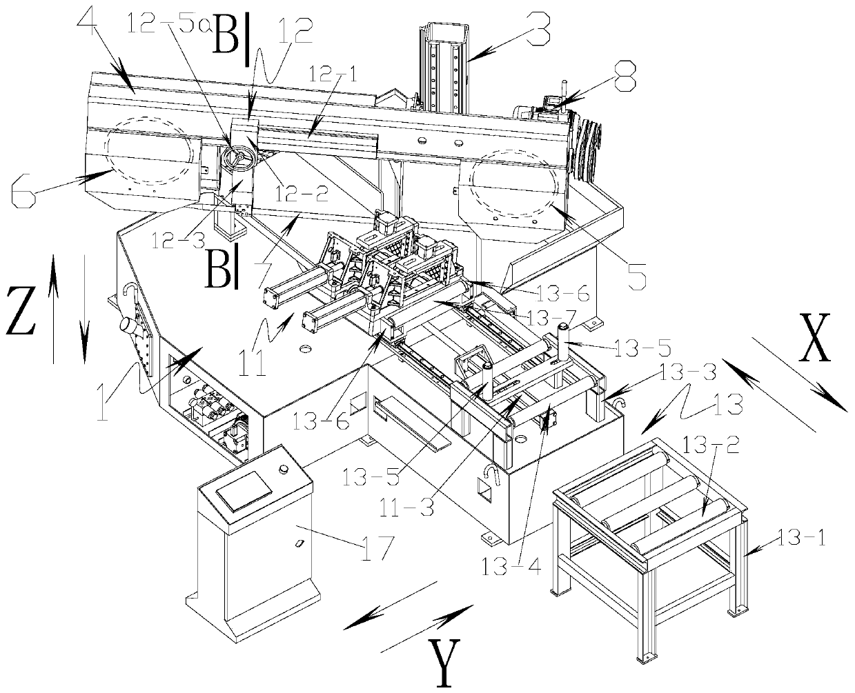
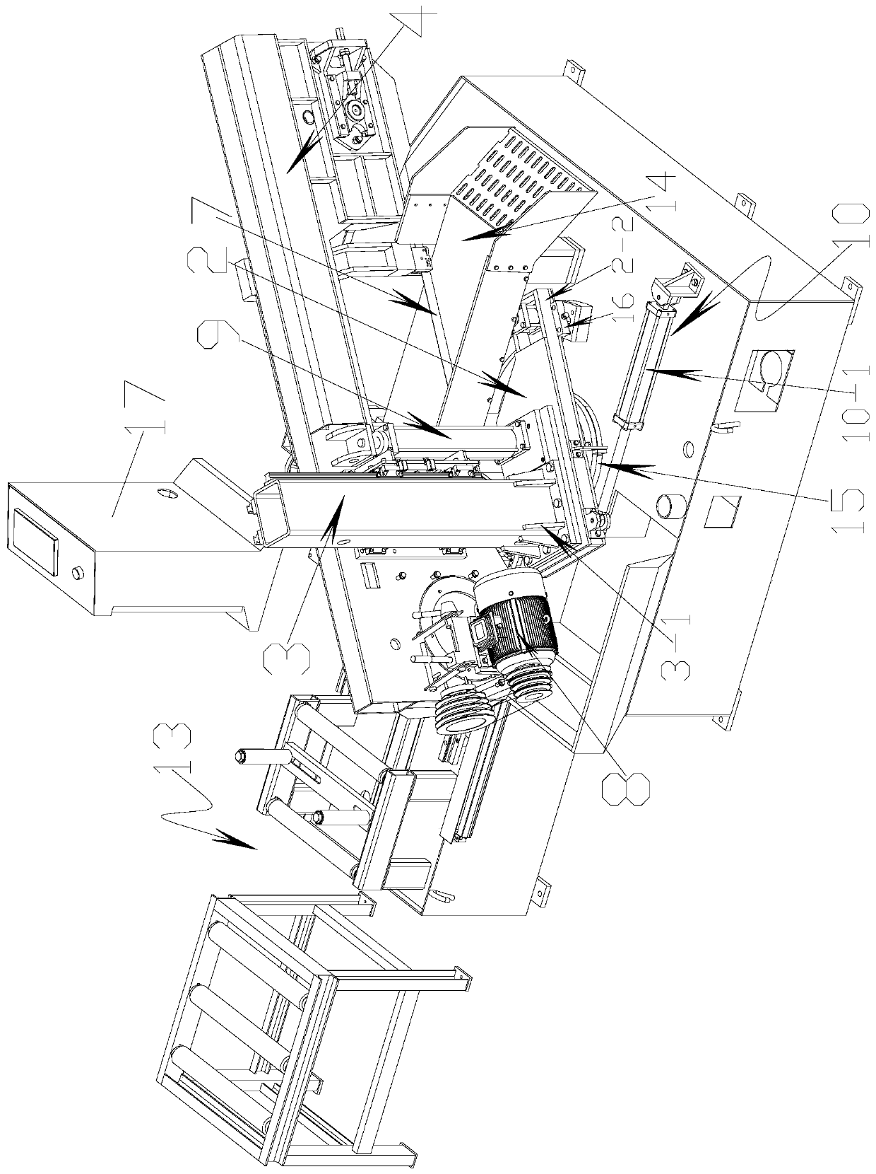
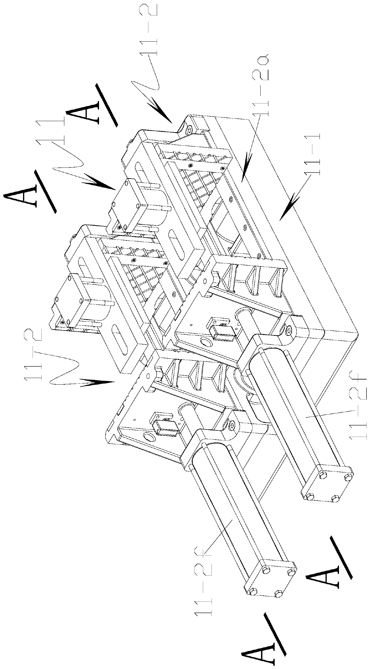
[0026] Refer to attached figure 1 , 2 , 3, 4, 7, 8: This new large-angle rotary horizontal band sawing machine includes a base frame 1, which is characterized in that: the base frame 1 is rotatably connected with a rotating disc 2, and the rotating disc 2 is fixed with a square pole 3 A set of first reinforcing ribs 3-1 is fixed between the bottom of the square pole 3 and the top of the rotating disc 2, the square pole 3 is provided with a sawing frame body 4 sliding on the square pole 3 along the "Z" direction, A driving pulley 5 and a driven pulley 6 are installed on the sawing frame body 4, a saw blade 7 is installed between the driving pulley 5 and the driven pulley 6, and the driving pulley 5 passes through the sawing frame body 4 on the first Driven by a servo motor 8, the rotating disk 2 is fixed with a first hydraulic cylinder 9 that drives the sawing frame body 4 to move up and down, and the base frame 1 is fixed with a drive mechanism 10 for driving the rotating di...

Embodiment 2

[0036] Refer to attached figure 1 , 2 , 3, 4, 5, 7, 8: This new large-angle rotating horizontal band sawing machine includes a base frame 1, a rotating disc 2 is connected to the base frame 1, and a square pole 3 is fixed on the rotating disc 2. A set of first reinforcing ribs 3-1 is fixed between the bottom of the pole 3 and the top of the rotating disk 2, and the square pole 3 is provided with a sawing frame body 4 that slides on the square pole 3 along the "Z" direction. A driving pulley 5 and a driven pulley 6 are installed on the frame body 4, a saw blade 7 is installed between the driving pulley 5 and the driven pulley 6, and the driving pulley 5 is cut by the first servo motor on the frame body 4. 8 drive, the first hydraulic cylinder 9 that drives the sawing frame body 4 to move up and down is fixed on the rotating disk 2, and the driving mechanism 10 for driving the rotating disk 2 to rotate is fixed on the base frame 1.

[0037] Driving mechanism 10 comprises the ...

Embodiment 3

[0046] Refer to attached figure 1 , 2 , 3, 4, 6, 7, 8: This new type of large-angle rotary horizontal band sawing machine includes a base frame 1, on which a rotating disc 2 is rotatably connected, and a square pole 3 is fixed on the rotating disc 2. A set of first reinforcing ribs 3-1 is fixed between the bottom of the pole 3 and the top of the rotating disk 2, and the square pole 3 is provided with a sawing frame body 4 that slides on the square pole 3 along the "Z" direction. A driving pulley 5 and a driven pulley 6 are installed on the frame body 4, a saw blade 7 is installed between the driving pulley 5 and the driven pulley 6, and the driving pulley 5 is cut by the first servo motor on the frame body 4. 8 drive, the first hydraulic cylinder 9 that drives the sawing frame body 4 to move up and down is fixed on the rotating disk 2, and the driving mechanism 10 for driving the rotating disk 2 to rotate is fixed on the base frame 1.

[0047] The driving mechanism 10 inclu...


PUM


Abstract

The invention discloses a novel large-angle rotation horizontal band sawing machine comprising a bed frame. The bed frame is rotatably connected with a rotating disk, and the rotating disk is fixedlyprovided with a square post bar; a group of first reinforcing ribs are fixed between the bottom of the square post bar and the top of the bed frame, and the square post bar is provided with a sawing frame body slid on the square post bar in the Z direction; the sawing frame body is provided with a driving belt wheel and a driven belt wheel, and a saw blade is installed between the driving belt wheel and the driven belt wheel; the driving belt wheel is driven by a first servo motor on the sawing frame body, and the rotating disk is fixedly provided with a first hydraulic oil cylinder for driving the sawing frame body to move up and down; and the bed frame is fixedly provided with a driving mechanism used for driving the rotating disk to rotate. The band sawing machine is ingenious and rational in structural design, and a workpiece can be cut by a large angle; and compared with a traditional sawing machine, the band sawing machine has the advantages of flexible sawing, large sawing angleand the like, and is worth popularizing and applying.

Description

technical field [0001] The invention relates to a sawing machine, in particular to a novel large-angle rotary horizontal band sawing machine. Background technique [0002] The sawing machine is a machine tool that realizes continuous cutting in processing and production. Usually, the sawing machine is used to cut large workpieces. The working method is to let the saw blade touch the workpiece, and then pull the saw blade down. Due to the different cutting positions of the workpiece, there are When it is necessary to cut the workpiece at an angle, the traditional band sawing machine is installed on a cylindrical rod to move up and down. The cylindrical rod can rotate, and then add to the sawing frame to strengthen the sawing frame. The support rod with strong bending strength can rotate in the circular arc direction on the sawing machine, so that the workpiece can be sawed at an angle. Since the support rod will also block the workpiece placement, this method greatly reduces ...

Claims


Application Information

Patent Timeline
Patent Type & Authority Applications(China)
IPC IPC(8): B23D55/02B23D55/00B23D55/08
CPCB23D55/02B23D55/00B23D55/08B23D55/088
Inventor 杜敏鹏
Owner 浙江锯力煌工业科技股份有限公司
Learn More