Auxiliary device for installation of grounding wire

An auxiliary device and grounding wire technology, applied in the direction of connection, conductive connection, electrical component connection, etc., can solve the problems of unreliable installation, difficult installation of grounding wire, low installation efficiency, etc., to achieve convenient connection, reliable installation, The effect of improving efficiency

Pending Publication Date: 2019-07-05
GUANGDONG POWER GRID CO LTD +1
View PDF0 Cites 0 Cited by
  • Summary
  • Abstract
  • Description
  • Claims
  • Application Information

AI Technical Summary

Problems solved by technology

[0003] In order to overcome the defects of difficult installation, low installation efficiency and unreliable installation of the grounding wire described in the above-mentioned prior art, the present invention provides an auxiliary device for installing the grounding wire, which facilitates the installation of the grounding wire of the three-phase busbar on the load side of the low-voltage main switch. effectively improve the efficiency of grounding wire installation

Method used


Image

  • Auxiliary device for installation of grounding wire
  • Auxiliary device for installation of grounding wire
  • Auxiliary device for installation of grounding wire

Examples


Embodiment 1

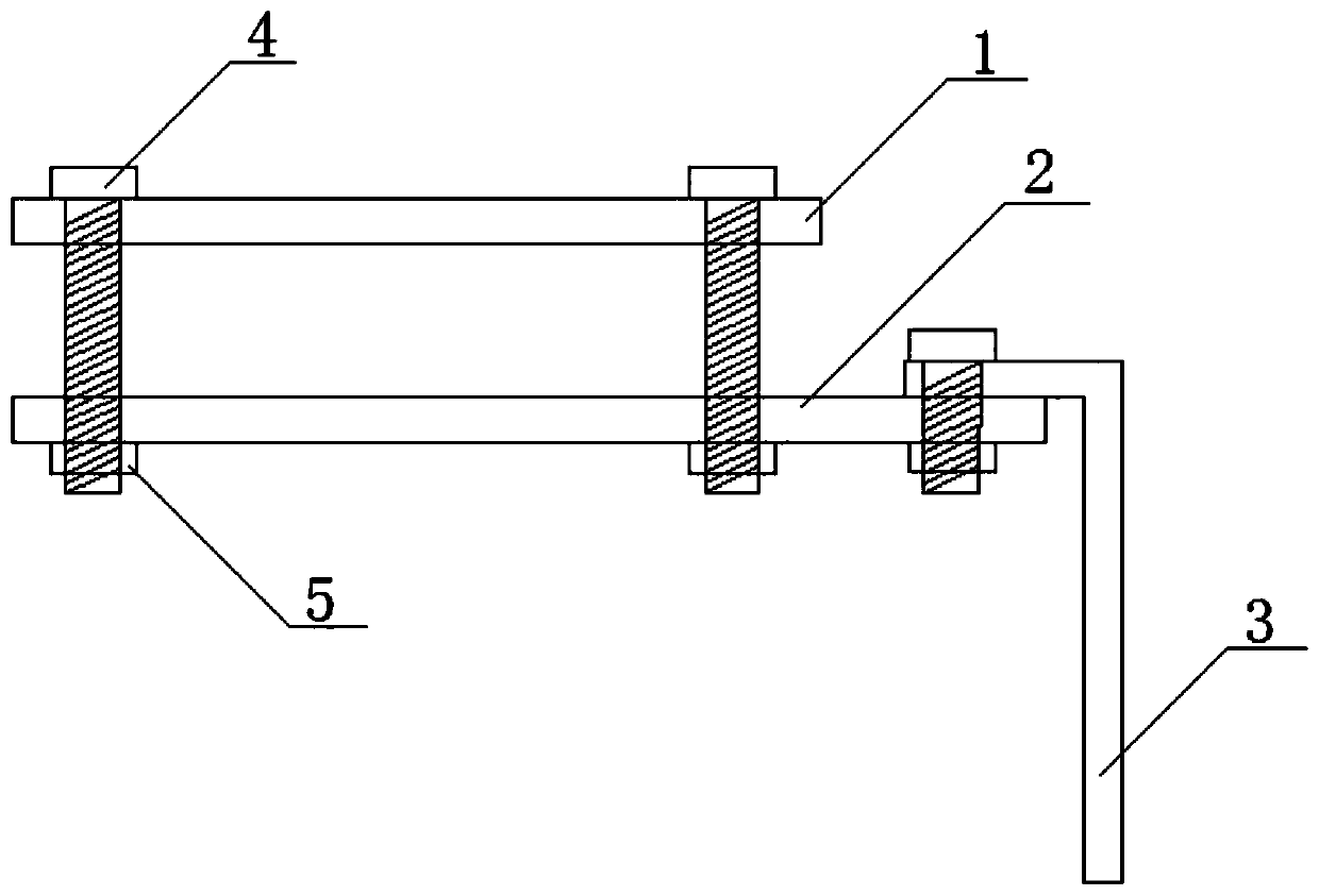
[0026] Such as figure 1 Shown is a schematic structural diagram of the grounding wire installation auxiliary device of this embodiment.

[0027] The grounding wire installation auxiliary device of this embodiment includes a first splint 1, a second splint 2, and a conductor 3, wherein the two ends of the first splint 1 are provided with screw holes, and the second splint 2 corresponds to the screw holes provided by the first splint 1. A screw hole is provided at the position of the hole, the conductor 3 is arranged at one end of the second splint 2 , and the angle between the conductor 3 and the second splint 2 is 90 degrees. Wherein, the first splint 1 and the second splint 2 are connected and fixed through the screw holes provided by the bolts 4 and the nuts 5 .

[0028] The conductor 3 in this embodiment is a copper row.

[0029] The first splint 1 and the second splint 2 in this embodiment are busbar splints made of copper.

[0030] In the specific implementation proces...

Embodiment 2

[0033] Such as figure 2 Shown is a schematic structural diagram of the grounding wire installation auxiliary device of this embodiment.

[0034] The grounding wire installation auxiliary device in this embodiment includes a first splint 1, a second splint 2, and a conductor 3, wherein the two ends of the first splint 1 are provided with screw holes, and the second splint 2 corresponds to the opening of the first splint 1. Screw holes are provided at the positions of the screw holes. Wherein the first splint 1 and the second splint 2 are connected and fixed through the screw holes provided by the bolts 4 and the nuts 5 .

[0035] In this embodiment, a screw hole is provided at the position where one end of the second splint 2 is connected to the conductor 3 , and the second splint 2 is connected and fixed to the conductor 3 through the screw hole provided by the bolt 4 and the nut 5 .

[0036] The conductor 3 in this embodiment is a copper row.

[0037] The first splint 1 a...

Embodiment 3

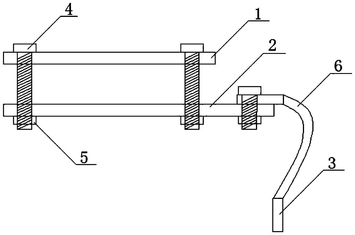
[0041] Such as figure 2 Shown is a schematic structural diagram of the grounding wire installation auxiliary device of this embodiment.

[0042] The grounding wire installation auxiliary device in this embodiment includes a first splint 1, a second splint 2, and a conductor 3, wherein the two ends of the first splint 1 are provided with screw holes, and the second splint 2 corresponds to the opening of the first splint 1. Screw holes are provided at the positions of the screw holes. Wherein the first splint 1 and the second splint 2 are connected and fixed through the screw holes provided by the bolts 4 and the nuts 5 .

[0043] The grounding wire installation auxiliary device in this embodiment also includes an annealed copper wire 6 for connecting with the conductor 3, and one end of the second splint 2 in this embodiment is provided with a screw hole, wherein one end of the annealed copper wire 6 is passed through a bolt 4 and the nut 5 are connected and fixed to the sec...


PUM


Abstract

The invention relates to the technical field of power equipment installation, and provides an auxiliary device for installation of a grounding wire. The auxiliary device comprises a first clamping plate and a second clamping plate, wherein screw holes are arranged in two ends of the first clamping plate, screw holes are arranged in the positions, corresponding to the screw holes arranged in the first clamping plate, of the second clamping plate, and a conductor used for being connected to the grounding wire is arranged at one end of the second clamping plate; and the first clamping plate and the second clamping plate are fixed to two sides of a to-be-installed grounding wire busbar by the screw holes through bolts and nuts, and the conductor is connected to the grounding wire. During a using process, the first clamping plate is arranged on one side of to-be-installed grounding wire equipment, the second clamping plate is arranged on the other side of the to-be-installed grounding wireequipment, the first clamping plate and the second clamping plate are in threaded connection and fastened by the screw holes through the bolts and the nuts, and the grounding wire is connected to theconductor arranged at one end of the second clamping plate, so that the installation of the grounding wire can be completed. According to the auxiliary device, the installation efficiency of the grounding wire can be effectively improved, and meanwhile, the grounding wire can be firmly installed.

Description

technical field [0001] The invention relates to the technical field of electric equipment installation, and more particularly, relates to an auxiliary device for installing a grounding wire. Background technique [0002] When the low-voltage power distribution cabinet is powered off, it is necessary to install the grounding wire on the load side busbar of the low-voltage main switch. However, due to the small distance between the three-phase busbars on the load side of the low-voltage main When the grounding wire is installed, it is difficult to install the grounding wire, and the installation time is long, the installation is not reliable, and other objects are prone to false grounding, which seriously affects work efficiency and personal safety. Contents of the invention [0003] In order to overcome the defects of difficult installation, low installation efficiency and unreliable installation of the grounding wire described in the above-mentioned prior art, the present ...

Claims


Application Information

Patent Timeline
Patent Type & Authority Applications(China)
IPC IPC(8): H01R11/05H01R11/01H01R4/46H01R4/30
CPCH01R4/30H01R4/46H01R11/01H01R11/05
Inventor 谭祖雁吴柏涛黄林海杨智诚胡志燊吴远章黎雄章刘忠勇翁治江胡庆钧李浩成黄胜冯报端庄卓文林伟枫
Owner GUANGDONG POWER GRID CO LTD
Why Eureka
Try Eureka