Actuator and light scanning device
A driver and beam-driving technology, which is applied in the direction of instruments, optics, optical components, etc., can solve the problems of inability to detect abnormal sensor output and increase beam width
- Summary
- Abstract
- Description
- Claims
- Application Information
AI Technical Summary
Problems solved by technology
Method used
Image

Examples
no. 1 approach 〉
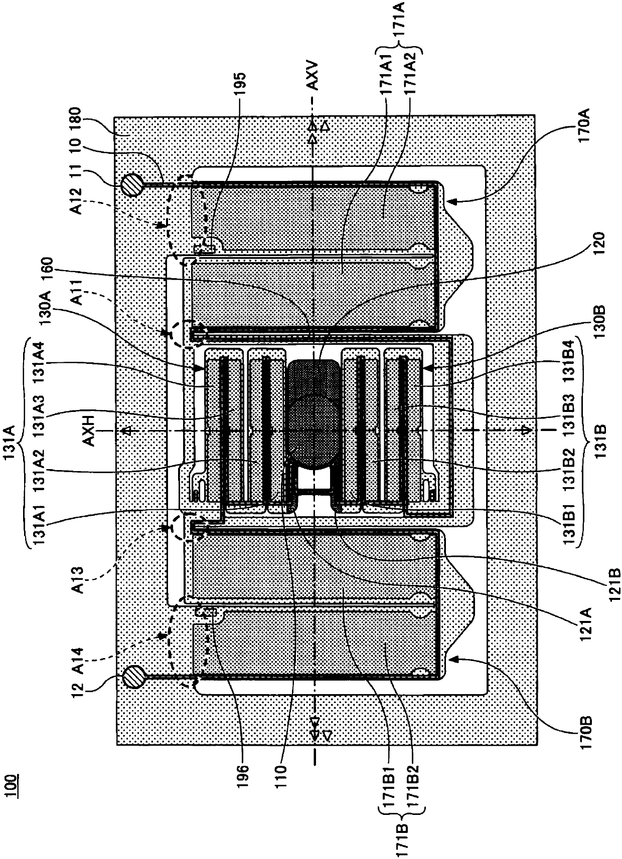
[0032] figure 1 It is a plan view showing an example of the optical scanning unit of the optical scanning device of the first embodiment on the upper surface side. The optical scanning unit 100 of this embodiment can be used by being housed in a box member such as a ceramic box and a box cover.
[0033] The light scanning unit 100 is a part that swings the mirror 110 to scan incident light of laser light irradiated from a light source, and is, for example, a MEMS mirror in which the mirror 110 is driven by a piezoelectric element. The incident laser light is incident on the mirror 110 provided in the light scanning unit 100, and the light emitted from the mirror 110 is scanned two-dimensionally.
[0034] Such as figure 1 As shown, the light scanning unit 100 has a mirror 110, a mirror support portion 120, connecting beams 121A, 121B, horizontal driving beams 130A, 130B, a movable frame 160, vertical driving beams 170A, 170B, and a fixed frame 180. The mirror 110 is supported on th...
no. 2 approach 〉
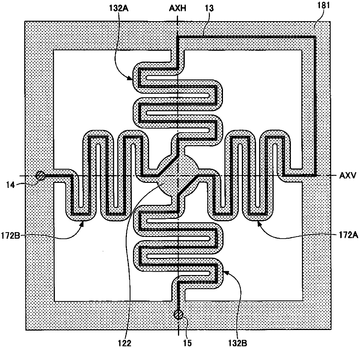
[0051] image 3 It is a plan view showing an upper surface side of an example of an optical scanning unit of the optical scanning device of the second embodiment. The light scanning unit has a mirror, a mirror support portion 122, horizontal driving beams 132A, 132B, vertical driving beams 172A, 172B, and a fixed frame 181. A mirror is supported on the upper surface of the mirror support portion 122. Horizontal drive beams 132A and 132B are arranged on both sides of the horizontal rotation axis AXH direction of the mirror support portion 122 that supports the mirror. One end of the horizontal drive beams 132A and 132B is connected to the mirror support portion 122, and the other The end is connected to the fixed frame 181. The horizontal driving beams 132A and 132B have a plurality of rectangular horizontal beams extending in the direction of the vertical rotation axis AXV orthogonal to the horizontal rotation axis AXH, and the ends of adjacent horizontal beams are connected w...
no. 3 approach 〉
[0067] Figure 7 It is a plan view showing an upper surface side of an example of the optical scanning unit of the optical scanning device of the third embodiment. In addition to providing a resistance change type temperature measuring resistor 28 on the path of the fault detection wiring pattern 10, and figure 1 The optical scanning section shown is the same. Figure 7 In the optical scanning unit of, a temperature measuring resistor 28 is provided on the movable frame 160 on the path of the failure detection wiring pattern 10. Normally, the resistance value of the failure detection wiring pattern 10 including the temperature measuring resistor 28 is monitored and used for the measurement of the temperature of the optical scanning unit. When the wiring pattern 10 for failure detection is broken and conduction is not detected, it is determined that breakage of the driving beam has occurred. As the temperature measuring resistor 28, a resistance variable thermistor can be used. ...
PUM
 Abstract
Description
Claims
Application Information
 - Generate Ideas
- Intellectual Property
- Life Sciences
- Materials
- Tech Scout
- Unparalleled Data Quality
- Higher Quality Content
- 60% Fewer Hallucinations
Browse by: Latest US Patents, China's latest patents, Technical Efficacy Thesaurus, Application Domain, Technology Topic, Popular Technical Reports.
© 2025 PatSnap. All rights reserved.Legal|Privacy policy|Modern Slavery Act Transparency Statement|Sitemap|About US| Contact US: help@patsnap.com