A pipeline radiographic flaw detection device and flaw detection method

A technology of ray flaw detection and ray flaw detector, which is applied in the direction of measuring devices, material analysis using wave/particle radiation, instruments, etc., can solve the problems of inconvenient measurement, different distances and angles, etc., achieve a wide range of applications and improve the effect of flaw detection Effect

Active Publication Date: 2020-03-13
海南民生公用管道检验有限公司
View PDF6 Cites 0 Cited by
  • Summary
  • Abstract
  • Description
  • Claims
  • Application Information

AI Technical Summary

Problems solved by technology

However, when the current pipeline ray flaw detector detects flaws on bent pipes, because the pipe is curved, the distance and angle between the flaw detector and the weld seam will be different when the ray flaw detector is on the inside and outside, which is not easy to measure.

Method used


Image

  • A pipeline radiographic flaw detection device and flaw detection method
  • A pipeline radiographic flaw detection device and flaw detection method
  • A pipeline radiographic flaw detection device and flaw detection method

Examples


Embodiment 1

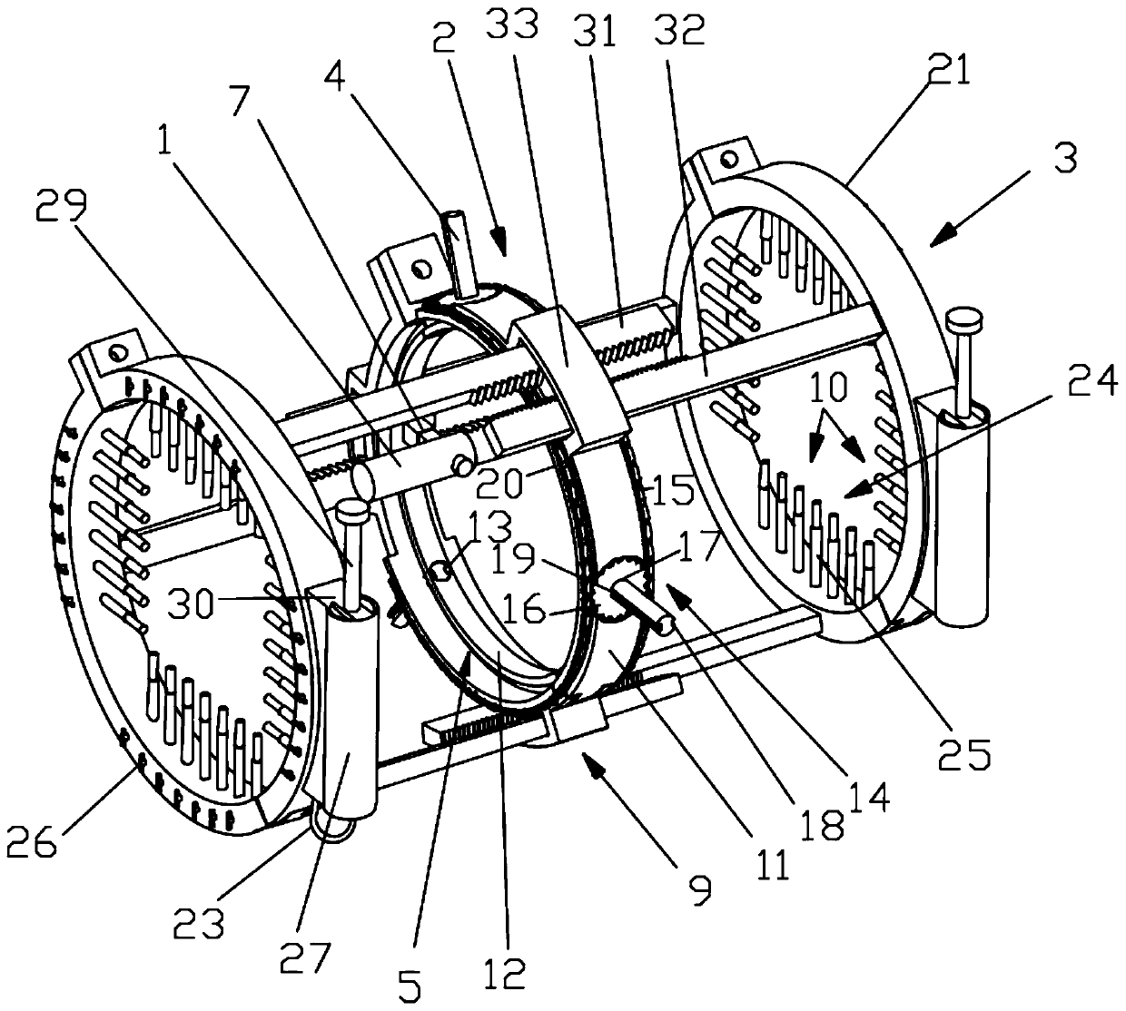
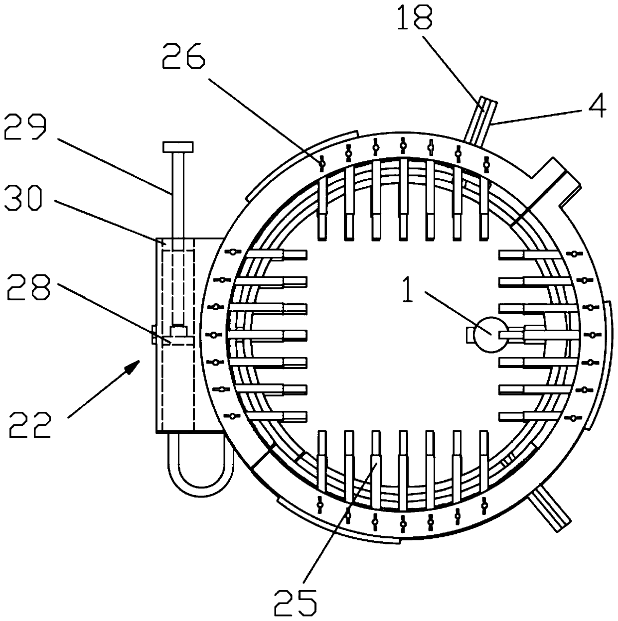
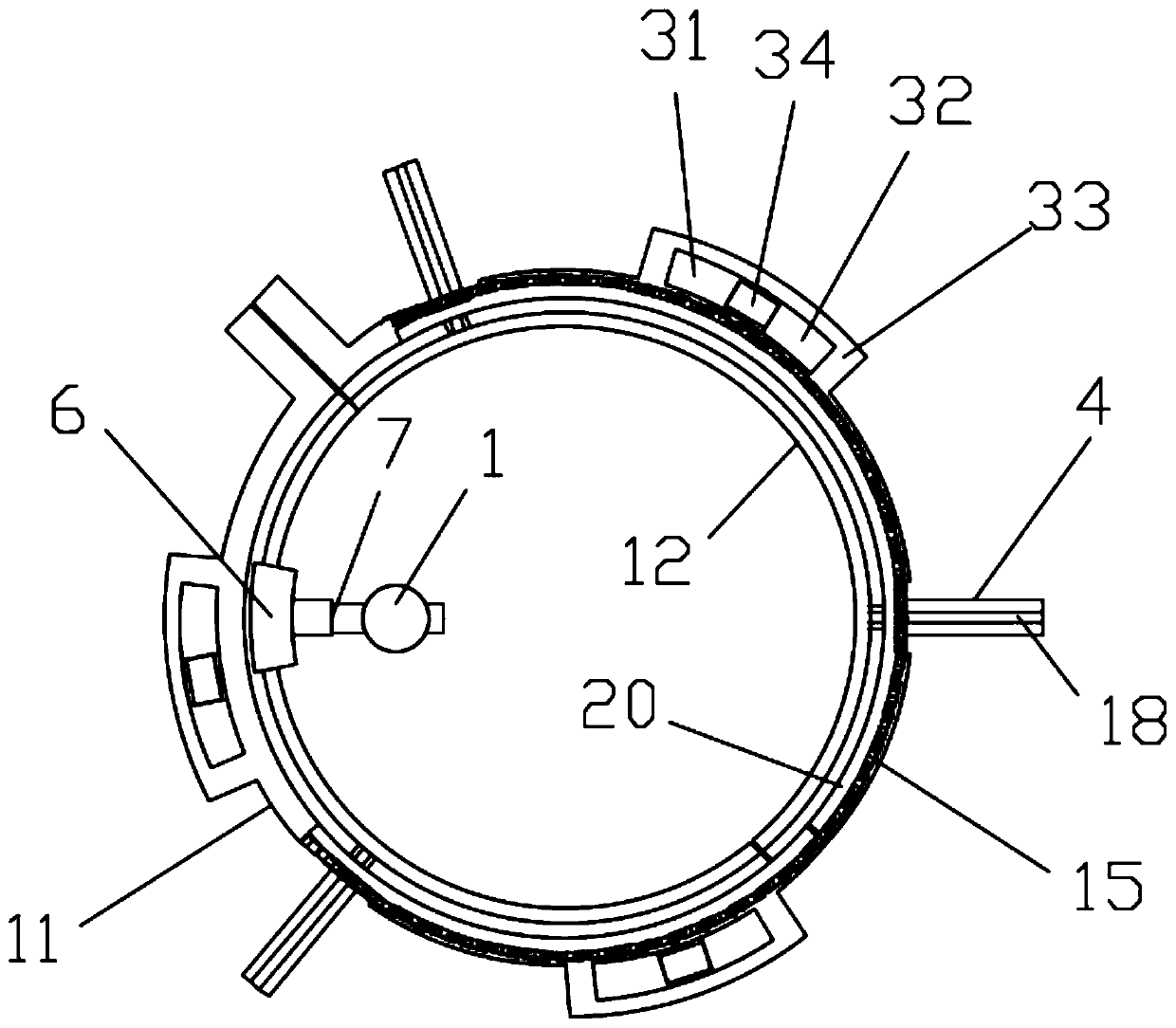
[0027] see Figures 1 to 4 , a pipeline radiographic flaw detection device, including a radiographic flaw detector 1, a positioning ring 2 and at least two fixing rings 3, the positioning ring 2 is provided with a plurality of positioning rods 4, and the positioning rods 4 and the positioning ring 2 are movably connected It is used to fix the welding seam in the middle of the positioning ring 2. The positioning ring 2 is provided with a ring slide rail 5, and a slide block 6 is provided on the ring slide rail 5. The slide block 6 passes through the telescopic rod 7 and the radiographic inspection The instrument 1 is fixedly connected, the fixed ring 3 is located on both sides of the positioning ring 2, and is connected with the positioning ring 2 through a linkage mechanism 9, and the fixed ring 3 is provided with a fixing ring for fixing itself on the pipeline. Fix the assembly 10.

[0028] Pass the pipe through the fixed ring 3 and the positioning ring 2, so that the plane ...

Embodiment 2

[0032] see Figures 1 to 4 , The difference between this embodiment and Embodiment 1 is that the positioning ring 2 is provided with a first threaded hole 13, and the positioning rod 4 is provided with a thread matched with the first threaded hole 13, and the positioning rod 4 passes through The transmission mechanisms 14 are mutually driven to rotate. Positioning rod 4 is provided with screw thread, and thread and threaded hole cooperate mutually, and positioning rod 4 is screwed into the center of positioning ring 2 when rotating positioning rod 4. The positioning rods 4 are mutually driven and rotated by the transmission mechanism 14. When one of the positioning rods 4 is rotated, the remaining positioning rods 4 rotate synchronously, and move and screw into the center of the positioning ring 2 to ensure that the welding seam is located in the middle of the positioning ring 2 without repeated adjustment. The depth to which each positioning rod 4 is screwed in.

[0033] Sp...


PUM


Abstract

The invention discloses a pipeline ray flaw detection device and a flaw detection method. The pipeline ray flaw detection device comprises a ray flaw detector, a positioning ring and at least two fixing rings; multiple positioning rods are arranged on the positioning ring, the positioning rod and the positioning ring are movably connected to fix a welding line in the middle of the positioning ring; an annular sliding rail is arranged in the positioning ring, a sliding block is arranged on the annular sliding rail, the sliding block is fixedly connected with the ray flaw detector through a telescopic lever; the fixing rings are located at two sides of the positioning ring and connected with the positioning ring through a connecting rod mechanism; and fixing modules for fixing the fixing rings on the pipeline are arranged on the fixing rings. In the process of ensuring the flow detection process of the bend, the detector and the welding line are maintained at the fixed angle and distance, and the flaw detection effect is improved.

Description

technical field [0001] The invention relates to the technical field of pipeline radiographic flaw detection, in particular to a pipeline radiographic flaw detection device and a flaw detection method. Background technique [0002] The pipeline radiographic flaw detection device uses rays to inspect the pipeline. During the detection process, it is necessary to keep the distance and angle between the pipeline radiographic flaw detection device and the weld consistent. However, when the current pipeline ray flaw detector detects flaws on bent pipes, since the pipe is curved, the distance and angle between the flaw detector and the weld seam will be different when the ray flaw detector is on the inside and outside, which is not easy to measure. Contents of the invention [0003] In view of the above prior art, the present invention provides a pipeline radiographic flaw detection device and flaw detection method, which ensures that the flaw detector and the weld seam maintain ...

Claims


Application Information

Patent Timeline
Patent Type & Authority Patents(China)
IPC IPC(8): G01N23/00
CPCG01N23/00G01N2223/309G01N2223/3303
Inventor 曾锐庄佳李志铭
Owner 海南民生公用管道检验有限公司
Why Eureka
Try Eureka