Laser positioning system

A technology of laser positioning and laser transmitter, applied in the field of positioning system, can solve problems such as large positioning error, and achieve the effects of reducing working time, reducing the size of the device, and reducing the radiation dose

Pending Publication Date: 2019-07-05
RES INST OF NUCLEAR POWER OPERATION +1
View PDF0 Cites 0 Cited by
  • Summary
  • Abstract
  • Description
  • Claims
  • Application Information

AI Technical Summary

Problems solved by technology

In order to complete the work as soon as possible, the staff will complete the counting process as soon as possible, resulting in a large positioning error

Method used


Image

  • Laser positioning system
  • Laser positioning system
  • Laser positioning system

Examples


Embodiment Construction

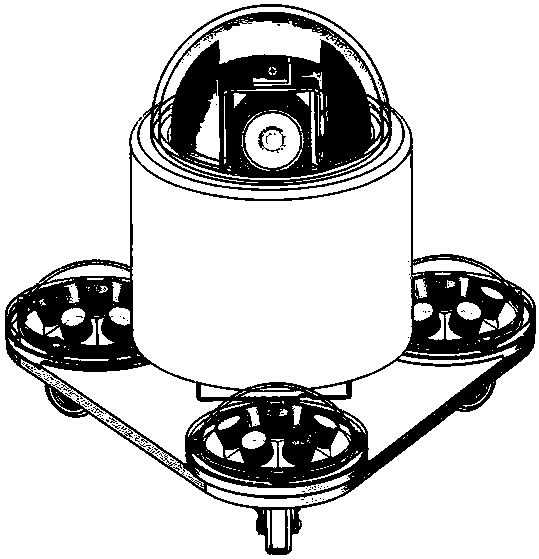
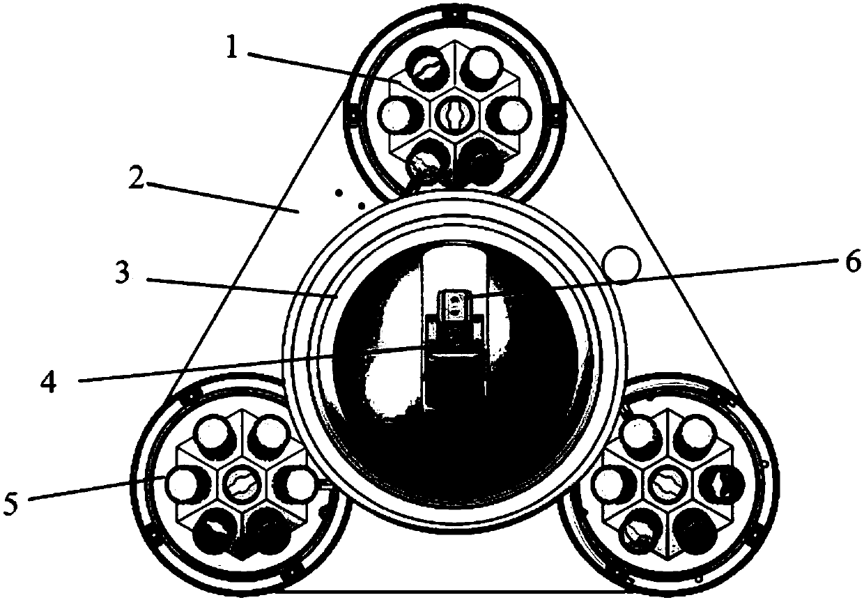
[0013] This system is mainly composed of laser transmitter, camera, light source system and mobile base.

[0014] As the main equipment of the whole system, the camera is equipped with a laser transmitter for 360° horizontal rotation and 90° vertical swing so that the reachable range of the laser point covers all the heat transfer tube holes, and cooperates with the main control software of the industrial computer to control the laser transmitter. Remote motion control and video surveillance. The laser emitter is fixed on the mounting bracket by locking bolts and integrated with the mounting bracket on the camera pan / tilt, and follows the camera pan / tilt to rotate and move without interfering with the camera pan / tilt movement. The laser master control software can control the position of the laser transmitter emission point relative to the tube plate hole and the field of view of the monitoring screen by controlling the movement direction of the camera pan-tilt, the movement s...


PUM


Abstract

The invention belongs to a positioning system, and particularly relates to a laser positioning system. The laser positioning system comprises a base component; the base component is a platform component and is used for carrying all other components; the base component is provided with a plurality of light source mechanisms; the light source mechanisms are uniformly distributed on the base component; the base component is also provided with a camera and a laser emitter; the laser emitter is used for emitting laser; the camera is used for shooting a region requiring to be positioned; on the basis of a recorded video, whether a positioned position meets requirements or not can be observed; the base component further comprises a movable mechanism; and the movable mechanism is used for moving the laser positioning system. The laser positioning system disclosed by the invention has the advantages of remote operation and simple and convenient use. With the laser positioning system adopted, the quantity of irradiation to which an operator is exposed can be greatly reduced.

Description

technical field [0001] This application belongs to a positioning system, in particular to a laser positioning system. Background technique [0002] The special single toe is a device installed on the tube sheet of the steam generator of the nuclear power plant. Since the working environment of the tube sheet of the steam generator is a high-radiation environment of the reactor, if it works for a long time, the radiation dose received by the staff will be too large, causing personal injury. as attached figure 1 As shown, the tube sheet used as the installation basis has many tube sheet holes, and it needs to be accurately positioned to the specified position during installation. In the traditional technology, the staff counts the specified number of holes in the unit of tube plate hole interval in high radiation environment to determine the installation position. In order to complete the work as soon as possible, the staff will complete the counting process as soon as poss...

Claims


Application Information

Patent Timeline
Patent Type & Authority Applications(China)
IPC IPC(8): G01C15/00
CPCG01C15/002
Inventor 龚卫民王晨胡卉桦郭友林
Owner RES INST OF NUCLEAR POWER OPERATION
Why Eureka
Try Eureka