


Quick Research
Generate reliable direction feasibility study reports for your R&D in just a few steps.

Technical Q&A
Discover and master advanced knowledge NOW. Basics, ideas, possibilities, all at once.

Find Solutions
As an expert in R&D theories, this can generate solutions to your technical problems instantly.

Evaluate Feasibility
Analyze your overall solution with one click, know your potential R&D risks in advance.

Monitor Landscape
Get weekly tech updates, stay abreast of the latest tech innovations and key insights.
Dehumidification and energy-saving drying device and method
A technology of drying equipment and drying area, which is applied in the direction of drying, drying machine, lighting and heating equipment, etc., and can solve the problems of high energy consumption, moisture return, and long time consumption
- Summary
- Abstract
- Description
- Claims
- Application Information
AI Technical Summary
Problems solved by technology
Method used
Image

Examples
Embodiment 1
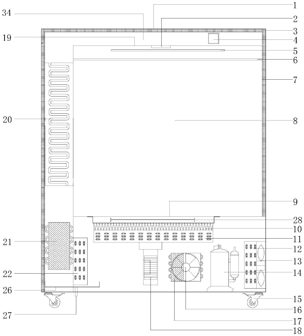
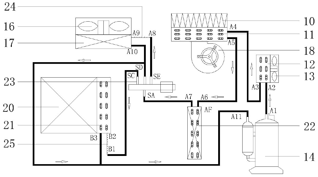
[0062] Example 1 Dehumidification and energy-saving drying equipment
[0063] Such as Figure 1-3 As shown, a dehumidification and energy-saving drying equipment in this embodiment includes an outer box 1 and an inner box 7, an insulation layer 3 arranged on the outer box 1, a controller 4 located on the outer box 1, and a Caster wheels 15, compressor 14, refrigerant pipeline, refrigerant running in the refrigerant pipeline, drying chamber, heating device for heating gas to form heated gas, and sending heated gas to the drying chamber under the outer box 1 The air supply device 18, the cooling release device for releasing the cooling capacity of the refrigerant, the heat recovery device 20 for recovering heat from the gas discharged from the drying chamber, the cooling device for condensing the gas, and the cooling device for releasing excess heat Heat releasing device, the drying chamber is provided with a drying area 8, the heat recovery device 20 includes a heat recovery d...
Embodiment 2
[0070] Embodiment 2 drying method
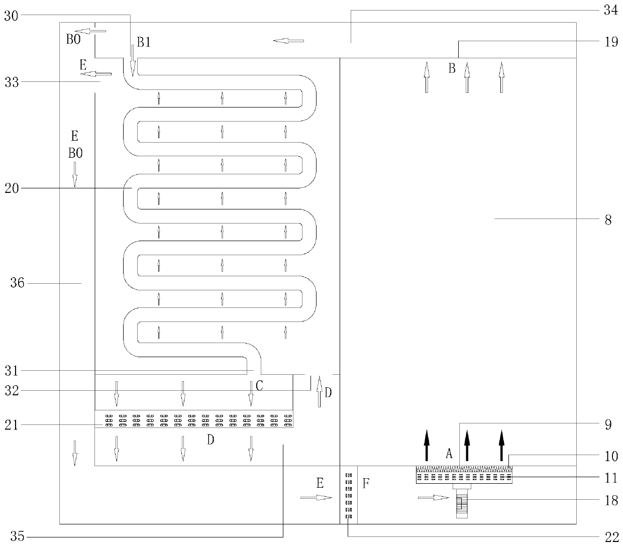
[0071] Such as Figure 1-3 As shown, this embodiment provides a drying method according to the dehumidification and energy-saving drying equipment in Embodiment 1. The drying method uses heated gas to dry the articles. The drying method specifically includes the following steps:
[0072] (1) Place the items to be dried in the preset drying zone 8, the drying zone 8 has a heating gas inlet and a heating gas outlet.
[0073] (2) The heating gas is passed into the drying zone 8 from the heating gas inlet, and after the articles in the drying zone 8 are heated, the drying zone 8 is discharged from the heating gas outlet, wherein the heating gas discharged from the drying zone 8 Divided into two shares.
[0074] (3) After dehumidifying and heating one of the two heated gases, it is re-introduced into the drying area. The gas to be dehumidified accounts for 20%-98% of the total volume of the gas output from the drying zone, preferably 30%-50%, ...
Embodiment 3
[0079] Embodiment 3 equipment running process
[0080] In practical application, the working process of dehumidification and energy-saving drying equipment is as follows:
[0081] When the dehumidification and energy-saving drying equipment is first started, it will first operate in the heat pump mode to raise the temperature of the drying zone 8 to the set temperature. The purpose of dry items.
[0082] Specifically, the following processes are included:
[0083] 1. When the equipment is started, the heat pump is used to quickly increase the temperature in the drying area:
[0084] 1. The heat pump operates to rapidly increase the temperature in the drying area, including the following steps:
[0085] (1) The compressor 14 is running to compress the refrigerant to form a high-temperature and high-pressure gaseous refrigerant that is discharged from the exhaust port of the compressor 14. The high-temperature and high-pressure gaseous refrigerant enters the first condensing ...
PUM
 Abstract
Description
Claims
Application Information
 - R&D Engineer
- R&D Manager
- IP Professional
- Industry Leading Data Capabilities
- Powerful AI technology
- Patent DNA Extraction
Browse by: Latest US Patents, China's latest patents, Technical Efficacy Thesaurus, Application Domain, Technology Topic, Popular Technical Reports.
© 2024 PatSnap. All rights reserved.Legal|Privacy policy|Modern Slavery Act Transparency Statement|Sitemap|About US| Contact US: help@patsnap.com