Automobile component punching forming die

An auto parts and stamping forming technology, applied in the field of auto parts stamping, can solve the problems of reduced efficiency, reduced work efficiency, inconvenient operation, etc., and achieves the effect of convenient repeated operation, reduced investment cost and improved work efficiency

Active Publication Date: 2019-07-05
JIANGSU XIANGHE ELECTRONICS SCI & TECH
View PDF7 Cites 1 Cited by
  • Summary
  • Abstract
  • Description
  • Claims
  • Application Information

AI Technical Summary

Problems solved by technology

[0003] After the stamping is completed, the mold formed after stamping is often pressed tightly in the die. Nowadays, the ejector pin is usually used to eject the mold, but the existing ejector pin is complicated to install, and it is impossible to grasp the jacking of the ejector pin. When the jacking height is too high, the ejector pin will damage the mold, increase the cost and reduce the efficiency. If the jacking height is too low, the mold cannot be ejected from the die, and the mold needs to be ejected again, which is very difficult to operate. Inconvenient, reduces work efficiency

Method used


Image

  • Automobile component punching forming die
  • Automobile component punching forming die
  • Automobile component punching forming die

Examples


Embodiment 1

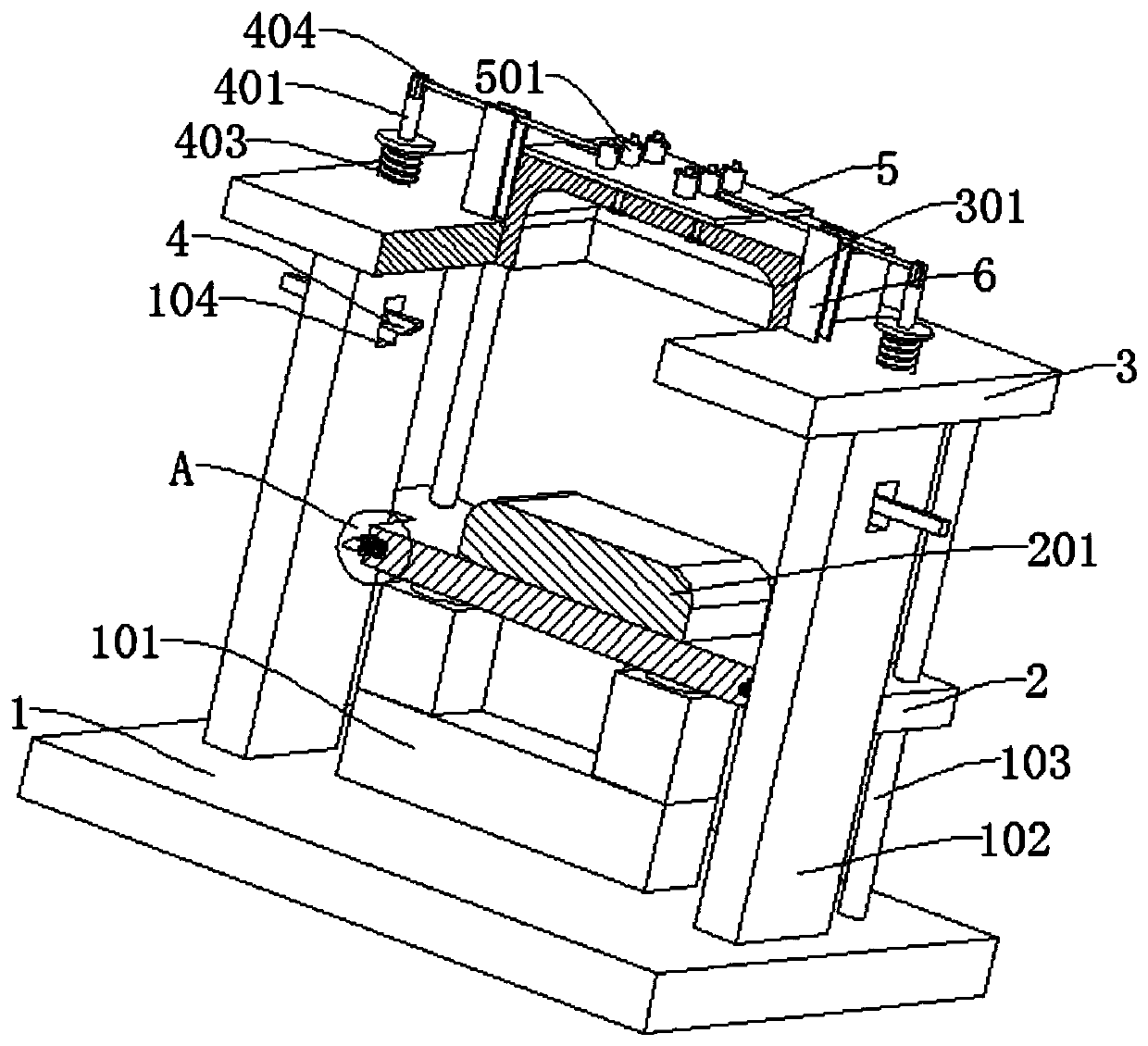
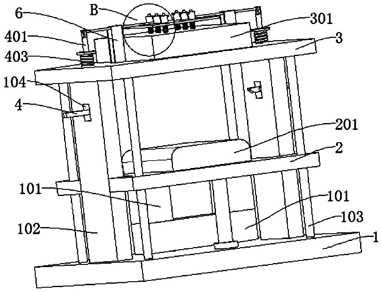
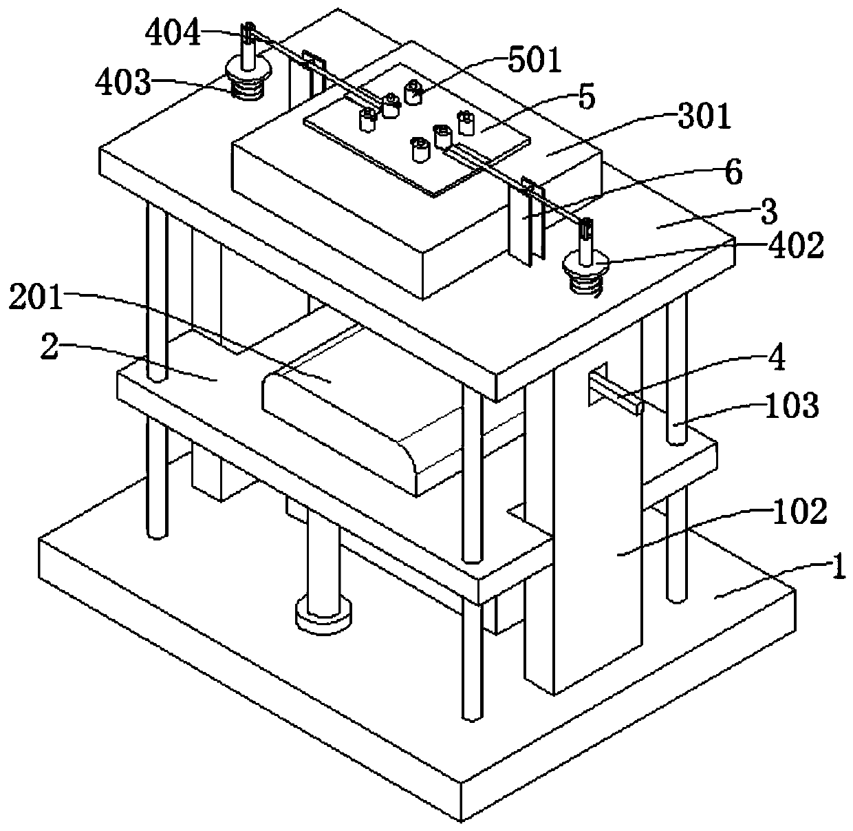
[0032] refer to Figure 1-8 , a stamping mold for auto parts, comprising a base plate 1, a first air pump 101, a punch 201, a top plate 3 and a die 301, the first air pump 101 is connected to the top of the base plate 1, and the die 301 is connected to the top plate 3, The end of the first air pump 101 away from the bottom plate 1 is connected to the slide plate 2, the punch 201 is connected to the outer wall of the slide plate 2, the inner wall of the die 301 is connected to the ejector pin 504, the top of the ejector pin 504 is connected to the pressure plate 5, and the top of the pressure plate 5 is connected to the The second air pump 501, the outer wall of the second air pump 501 is respectively connected with a vent valve 502 and a one-way valve 503, the end of the ejector pin 504 away from the die 301 passes through the second air pump 501 and is connected with a piston 507, the ejector pin 504 is placed One end in the die 301 is connected with a top sheet 506 .

[003...

Embodiment 2

[0036] refer to Figure 1-8 , a stamping mold for auto parts, comprising a base plate 1, a first air pump 101, a punch 201, a top plate 3 and a die 301, the first air pump 101 is connected to the top of the base plate 1, and the die 301 is connected to the top plate 3, The end of the first air pump 101 away from the bottom plate 1 is connected to the slide plate 2, the punch 201 is connected to the outer wall of the slide plate 2, the inner wall of the die 301 is connected to the ejector pin 504, the top of the ejector pin 504 is connected to the pressure plate 5, and the top of the pressure plate 5 is connected to the The second air pump 501, the outer wall of the second air pump 501 is respectively connected with a vent valve 502 and a one-way valve 503, the end of the ejector pin 504 away from the die 301 passes through the second air pump 501 and is connected with a piston 507, the ejector pin 504 is placed One end in the die 301 is connected with a top sheet 506 .

[0037]...

Embodiment 3

[0041] refer to Figure 1-7 , a stamping mold for auto parts, which is basically the same as that of Embodiment 1. Further, a groove is dug in the slot, a slider 202 is connected in the groove, and a baffle 203 is connected to the outer wall of the slider 202. Both the block 202 and the baffle 203 are slidably connected in the groove, and a first spring 204 is connected between the baffle 203 and the inner wall of the groove.

[0042] refer to Figure 1-4 , the outer wall of the limiting plate 102 is dug with a concave hole 104, the inner wall of the concave hole 104 is connected with a fixed shaft 105, the outer wall of the fixed shaft 105 is connected with a pull rod 4 matching with the slider 202, and the pull rod 4 is slidably connected to the concave hole through the fixed shaft 105 104 inside.

[0043] refer to Figure 4 and 7 , The outer walls of the slider 202 and the pull rod 4 are provided with inclined surfaces that cooperate with each other.

[0044] refer to ...


PUM


Abstract

The invention discloses an automobile component punching forming die, and belongs to the technical field of automobile component punching. The automobile component punching forming die comprises a bottom plate, a first air pump, a male die, a top plate and a female die. The first air pump is connected to the top of the bottom plate, the female die is connected to the top plate, the end, away fromthe bottom plate, of the first air pump is connected with a sliding plate, the male die is connected to the outer wall of the sliding plate, ejector pins are connected to the inner wall of the femaledie, the tops of the ejector pins are connected with a pressing plate, the top of the pressing plate is connected with second air pumps, and the outer wall of each second air pump is connected with agas releasing valve and a one-way valve; and the ends, away from the female die, of the ejector pins penetrate through the second air pumps and are connected with pistons, and the ends, arranged in the female die, of the ejector pins are connected with ejector sheets. Through the arrangement of the second air pumps, it can be guaranteed that the stretching length of the ejector pins in the motionprocess is proper, and the situation that the ejector pins jack the dies to damage is avoided; and cost is reduced, manual drawing is avoided, the labor intensity is lowered, the work efficiency is improved, and repeated operation is convenient.

Description

technical field [0001] The invention relates to the technical field of stamping of auto parts, in particular to a stamping mold for auto parts. Background technique [0002] Stamping forming refers to the application of external force to plates, strips, pipes and profiles by means of presses and molds. The stamping device below applies pressure to the steel through the punch to cause plastic deformation or separation to obtain the desired shape and size. For auto parts, stamping blanks are mainly hot-rolled and cold-rolled steel sheets and strips. [0003] After the stamping is completed, the mold formed after stamping is often pressed tightly in the die. Nowadays, the ejector pin is usually used to eject the mold, but the existing ejector pin is complicated to install, and the jacking of the ejector pin cannot be grasped. When the jacking height is too high, the ejector pin will damage the mold, increase the cost and reduce the efficiency. If the jacking height is too low,...

Claims


Application Information

Patent Timeline
Patent Type & Authority Applications(China)
IPC IPC(8): B21D37/10B21D45/02B21D55/00
CPCB21D37/10B21D45/02B21D55/00
Inventor 钱应平周志明王刚
Owner JIANGSU XIANGHE ELECTRONICS SCI & TECH
Why Eureka
Try Eureka