Quantitative liquid transfer device

A technology for transferring devices and liquids, which can be used in fluid controllers, measuring tubes/pipettes, laboratory utensils, etc.

Pending Publication Date: 2019-07-05
DEMODE SUZHOU MACHINERY TECH CO LTD
View PDF0 Cites 3 Cited by
  • Summary
  • Abstract
  • Description
  • Claims
  • Application Information

AI Technical Summary

Problems solved by technology

At present, when the liquid is divided into multiple equal parts, or the liquid is quantitatively divided into different volumes, a separate operation is required, and the function of quantitatively dividing the liquid into multiple parts cannot be realized at one time.

Method used


Image

  • Quantitative liquid transfer device
  • Quantitative liquid transfer device
  • Quantitative liquid transfer device

Examples


Embodiment 1

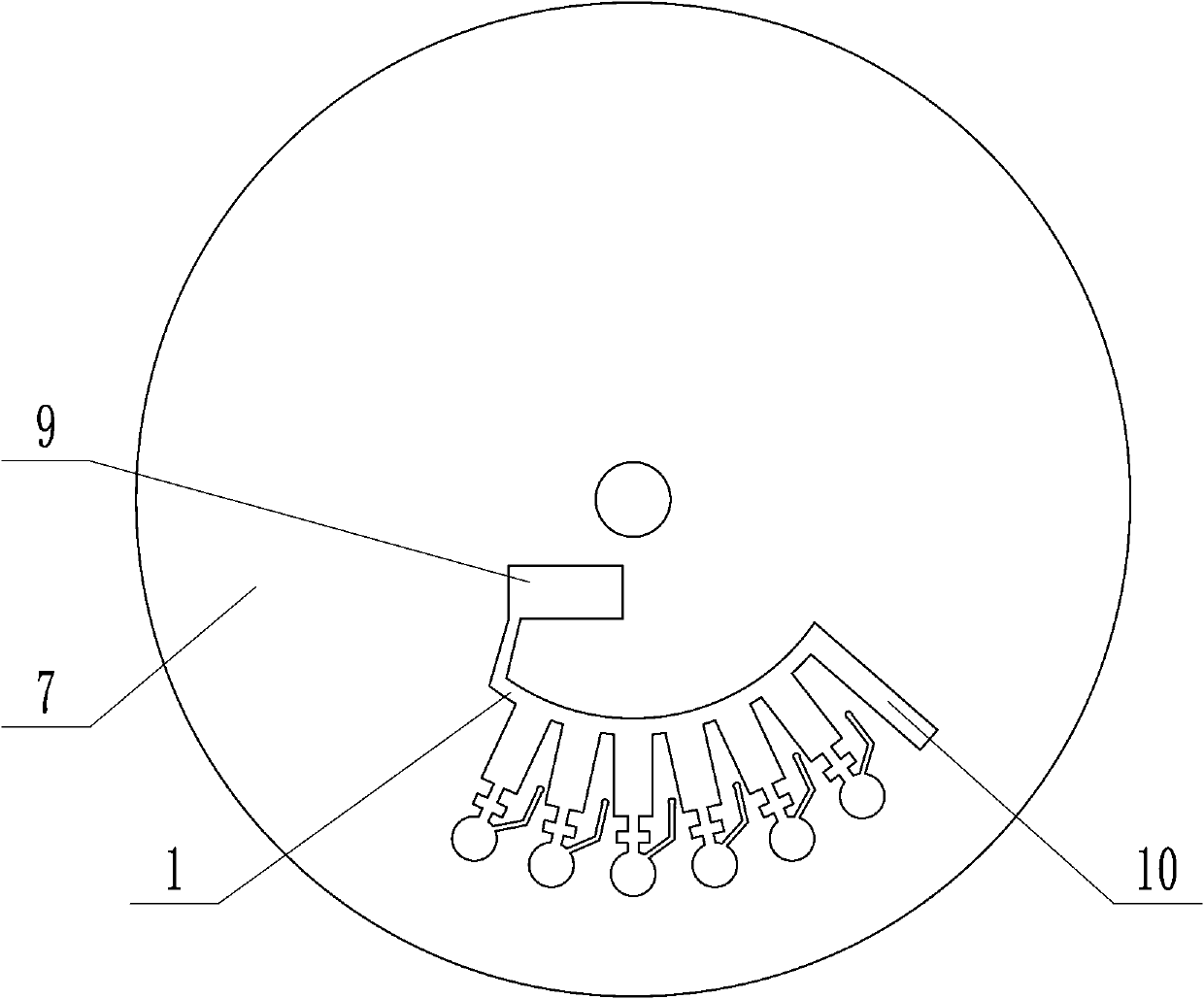
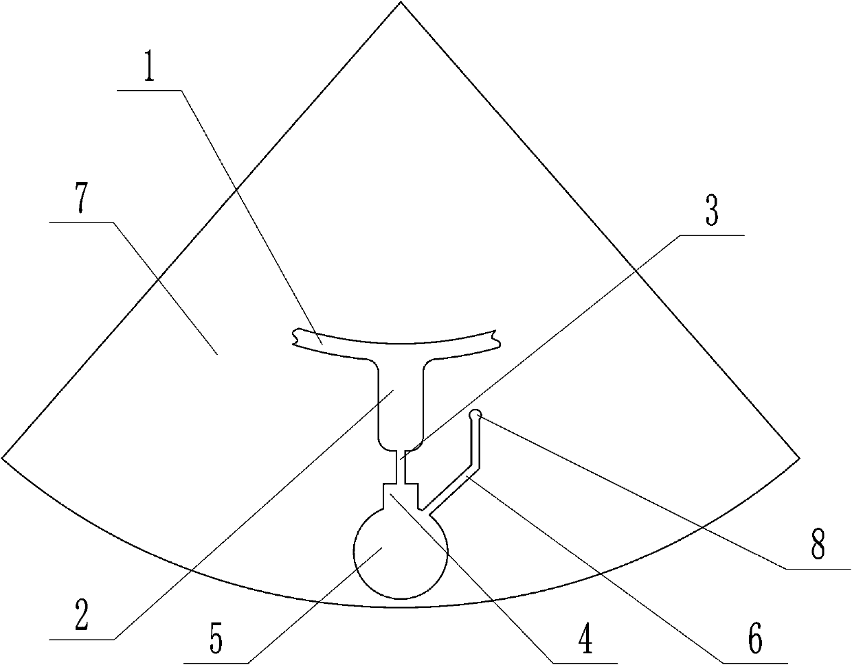
[0016] Embodiment 1: as attached figure 1 , 2 As shown, the present invention includes a rotating reagent disk 7, a third chamber 9 arranged on the rotating reagent disk 7, a third flow channel 1 communicated with the third chamber 9, and several liquid delivery channels communicated with the third flow channel 1 structure and the fourth chamber 10 arranged at the end of the third channel 1 . The first chambers 2 of the plurality of liquid delivery structures are at the same distance from the rotation axis of the rotating reagent disk 7 . The third chamber 9, the third flow channel 1, and the liquid delivery structure are set outwards in sequence relative to the rotation axis of the reagent disk. When the rotating reagent disk 7 rotates, the liquid in the third chamber 9 enters the liquid through the third flow channel 1. The delivery structure, when all the first chambers 2 of the liquid delivery structure are filled, the remaining liquid enters the fourth chamber 10 .

[...

Embodiment 2

[0020] Embodiment 2: as attached image 3 As shown, on the basis of Embodiment 1, keep other structures unchanged, only change the position of the variable diameter chamber 4, and make the variable diameter chamber 4 connect with the second chamber 5 to form a chamber, and the embodiment can also be realized 1 effect.

[0021] When the present invention is in use, an appropriate amount of liquid is first added to the third chamber, and the rotating reagent disk rotates at a speed lower than a certain speed threshold. In this case, the liquid entering the first chamber 2 will not open the capillary passive valve, When the rotational speed is higher than the threshold, the liquid in the first chamber 2 will open the capillary passive valve, and the liquid will enter the second chamber 5 . In the case of low speed, the liquid in the third chamber 9 is thrown out into the third flow channel 1, and then transported forward along the third flow channel 1, and then enters into multi...


PUM


Abstract

The invention relates to a quantitative liquid transfer device. The quantitative liquid transfer device comprises a rotating reagent tray, a third chamber, a third flow channel, a plurality of liquidconveying structures and a fourth chamber, wherein the liquid conveying structures comprise first chambers, second chambers and diameter varying chambers, and the inner diameters of the diameter varying chambers are greater than that of a first flow channel to form capillary tube passive valves; when the rotating reagent tray rotates, liquid located in the third chamber flows out through the thirdflow channel under the action of the centrifugal force, then the first chambers of the liquid conveying structures are filled with the liquid in sequence, the excess liquid enters the fourth chamber;when the rotation speed of the rotating reagent tray is controlled to be lower, due to the action of the capillary tube passive valve, the liquid stays in the first chambers and cannot enter the second chambers, when the rotation speed is increased, the centrifugal force in the first chambers is increased, the liquid breaks through the limitation of the capillary tube passive valves and enters the second chambers; by adjusting the sizes of the first chambers, it can be achieved that the liquid is taken out quantitatively and conveyed into the second chambers, and quantitative conveying of theliquid is achieved.

Description

technical field [0001] The invention relates to a liquid quantitative transfer device. Background technique [0002] When performing sample testing in the life sciences and medical fields, it is necessary to mix the sample with a variety of different reagents, or perform a mixed test with a specific reagent in different proportions to achieve sufficient detection of the sample. Quantitative collection of samples is often required. At present, when the liquid is divided into multiple equal portions, or the liquid is quantitatively divided into different volumes, a separate operation is required, and the function of quantitatively dividing the liquid into multiple portions cannot be realized at one time. Contents of the invention [0003] The technical problem to be solved by the present invention is to provide a liquid quantitative transfer device that can quantitatively divide liquid into multiple portions at one time. [0004] The technical scheme adopted in the present...

Claims


Application Information

Patent Timeline
IPC IPC(8): B01L3/02
CPCB01L3/0289B01L2400/0406
Inventor 张涛
Owner DEMODE SUZHOU MACHINERY TECH CO LTD
Why Eureka
Try Eureka