A dry powder mixing device

A mixing device and powder technology, applied in mixers, transportation, packaging, dissolution, etc., can solve problems such as troublesome maintenance and replacement, poor continuity, troublesome maintenance, etc., and achieve convenient and labor-saving maintenance, good social significance, and flexible and convenient use Effect

Active Publication Date: 2021-06-18
知弗(上海)科技股份有限公司
View PDF0 Cites 0 Cited by
  • Summary
  • Abstract
  • Description
  • Claims
  • Application Information

AI Technical Summary

Problems solved by technology

[0002] At present, with the development of passivation technology, the composition of powder passivation products is becoming more and more complex, and the powder mixing process is becoming more and more important. In the prior art, the mixing method is relatively simple, one is to use multi-arm stirring The net stirs the raw materials for forced mixing, most of which are funnel-shaped structures. After the raw materials are put in from the top, they are stirred and mixed and then discharged from the bottom. The continuity is good, and the feeding can be carried out without interruption. There is a dead angle between the net and the mixing tank, and the mixing path is shortened when the volume is small, which has a certain impact on the mixing effect. At the same time, it is troublesome to repair and replace the metal mixing net when it is deformed and damaged. In addition, when the metal surface is worn, the metal The powder falling and doping in the raw material will also affect the purity of the raw material. The other is the drum rolling type, which has a better mixing effect, but it is bulky, the stirring efficiency is low, the mechanical structure is complicated and maintenance is troublesome, and the continuity is poor. The second charge can only be made after the mixing is completed. Therefore, in order to better realize the production of powder passivation products, it is necessary to design a new mixing device that can combine the advantages of the two mixers.

Method used


Image

  • A dry powder mixing device
  • A dry powder mixing device
  • A dry powder mixing device

Examples


Embodiment Construction

[0013] The technical solution of this patent will be further described in detail below in conjunction with specific embodiments.

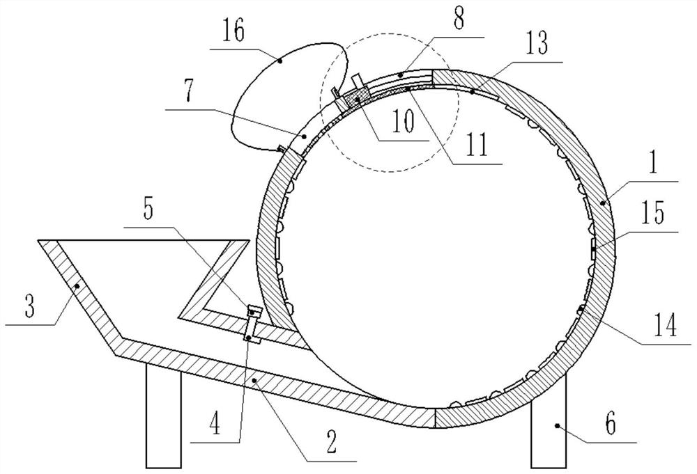
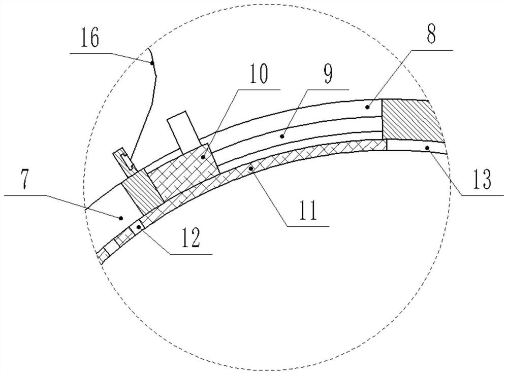
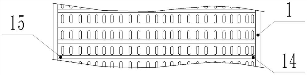
[0014] see Figure 1-3 , a dry powder mixing device, including a mixing cylinder 1 and a feeding tank 2, the feeding tank 2 is arranged obliquely and its lower right end is smoothly connected with the lower left end of the mixing cylinder 1, and the upper left end of the feeding tank 2 is connected with a filler The bucket 3 and the upper end wall of the feed tank 2 are fixedly embedded with a number of nozzles 4, the air outlets 7 of the nozzles 4 are parallel to the feed tank 2 and point to the inside of the mixing cylinder 1, and the air inlets of the nozzles 4 are all led out of the feed tank 2 And it is connected with the Laval nozzle 5, which is connected with the gas storage equipment such as the gas storage tank. 2. The powder falling into the mixing cylinder 1 is tumbled and mixed along its inner wall in the mixing cylinder 1. Using high-...


PUM


Abstract

The invention discloses a dry powder mixing device, which comprises a mixing cylinder and a feeding tank, the upper end wall of the feeding tank is fixedly embedded with several nozzles, and the air inlets of the nozzles are all connected with Laval nozzles; the mixing cylinder There is an air outlet and an adjustment port on the upper left cylinder wall. There is a slideway in the adjustment opening. A slider is slidably connected to the slideway. The lower end of the slider is fixedly connected with the baffle plate. Arc-shaped plate structure, the baffle plate is composed of an air outlet part and a sealing part, the air outlet part is matched with the air outlet, and a number of air outlet mesh holes are opened on the wall, and the inner wall of the mixing cylinder is also provided with a storage groove for receiving the sealing part on the right side of the adjustment port ; The inner wall of the mixing cylinder is fixedly connected with a disturbing flow bar and a splitter plate except for the air outlet, the regulating port and the receiving groove. The present invention integrates the advantages of the existing two mixers, and has good mixing effect and high efficiency. Good continuity, simple structure and convenient care.

Description

technical field [0001] The invention relates to a mixing device, in particular to a dry powder mixing device. Background technique [0002] At present, with the development of passivation technology, the composition of powder passivation products is becoming more and more complex, and the powder mixing process is becoming more and more important. In the prior art, the mixing method is relatively simple, one is to use multi-arm stirring The net stirs the raw materials for forced mixing, most of which are funnel-shaped structures. After the raw materials are put in from the top, they are stirred and mixed and then discharged from the bottom. The continuity is good, and the feeding can be carried out without interruption. There is a dead angle between the net and the mixing tank, and the mixing path is shortened when the volume is small, which has a certain impact on the mixing effect. At the same time, it is troublesome to repair and replace the metal mixing net when it is def...

Claims


Application Information

Patent Timeline
Patent Type & Authority Patents(China)
IPC IPC(8): B01F13/02B01F15/00B01F33/40
CPCB01F33/405B01F35/43B01F35/55B01F35/184
Inventor 祝亚琴
Owner 知弗(上海)科技股份有限公司
Why Eureka
Try Eureka