
Cloth bag deduster for waste gas treatment

A bag filter and waste gas treatment technology, applied in chemical instruments and methods, dispersed particle filtration, combined devices, etc., can solve problems affecting the normal production and operation of enterprises, economic losses of enterprises, etc., and achieve the effect of reducing losses and prolonging service life.

Inactive Publication Date: 2019-07-05
任井斌
View PDF0 Cites 0 Cited by
  • Summary
  • Abstract
  • Description
  • Claims
  • Application Information

AI Technical Summary

Problems solved by technology

[0002] The bag filter is a dry dust filter device; it is suitable for collecting fine, dry, non-fibrous dust; the filter bag is made of textile filter cloth or non-woven felt, and uses the filtering effect of the fiber fabric to filter the dust The gas is filtered. When the dusty gas enters the bag filter, the dust with large particles and specific gravity will settle down due to the effect of gravity and fall into the ash hopper. When the gas containing finer dust passes through the filter material, the dust will be blocked. The existing bag filter needs to be closed when the filter bag is maintained or the bag needs to be replaced due to broken bags, and then the bag cage can be taken out, and then the filter bag can be maintained or replaced. , downtime will inevitably affect the normal production and operation of the enterprise, and even cause serious economic losses to the enterprise

Method used


Image

  • Cloth bag deduster for waste gas treatment
  • Cloth bag deduster for waste gas treatment
  • Cloth bag deduster for waste gas treatment

Examples


Embodiment Construction

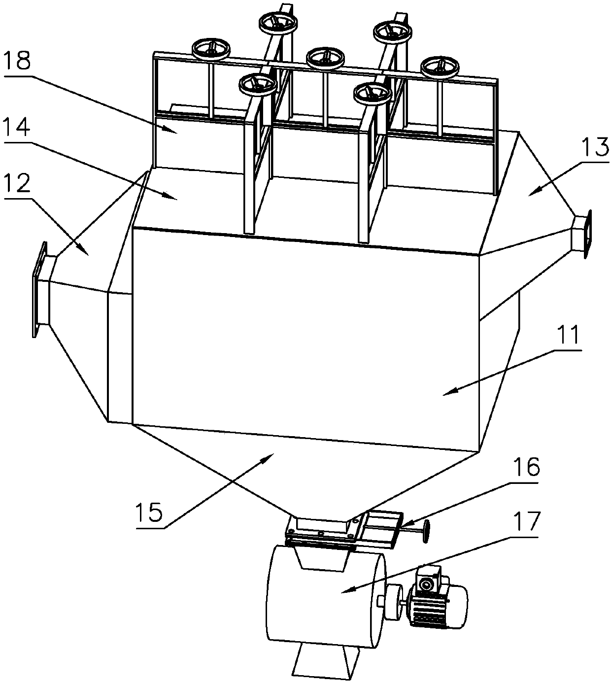
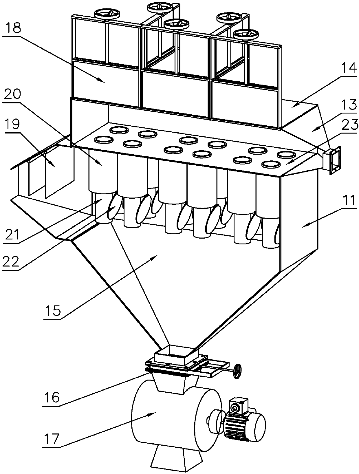
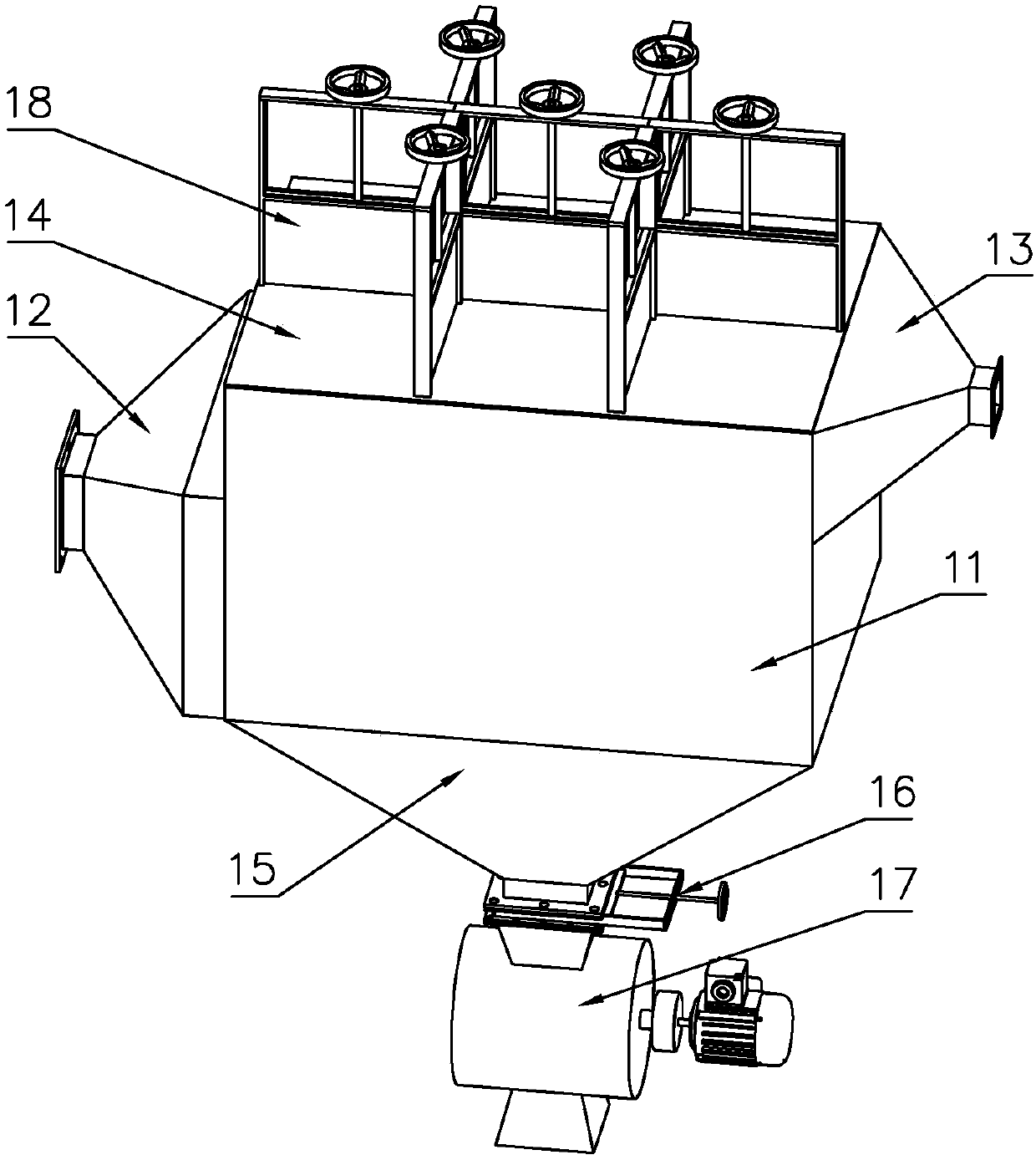
[0017] For the convenience of those skilled in the art to understand, the following in conjunction with the attached Figure 1-2 , to further specifically describe the technical solution of the present invention.

[0018] A cloth bag dust collector for waste gas treatment, comprising a housing 11, an air inlet 12, an air outlet 13, a cover plate 14, a dust collecting bucket 15, an ash unloading valve 17, a flapper valve II 18, a cloth bag 21, and a flower plate 23. There is an air inlet 12 on one side of the housing 11, the air inlet 12 is in the shape of a cone, the large end of the air inlet 12 is fixedly connected with the housing 11, the cone-shaped air inlet 12 is conducive to the uniformity of exhaust gas inside the housing 11 Distribution; the other side of the housing 11 is provided with an air outlet 13, the air outlet 13 is cone-shaped, the large end of the air outlet 13 is fixedly connected with the housing 11, and the cone-shaped air outlet 13 is conducive to dust ...


PUM


Abstract

The invention discloses a cloth bag deduster for waste gas treatment. The cloth bag deduster comprises a shell, an air inlet, an air outlet, a cover plate, a dust hopper, a cindervalve, board plug valves II, cloth bags and a tubesheet. One side of the shell is equipped with the conical bucket shaped air inlet, and the big end of the air inlet is in fixed connection with the shell; the other side of the shell is equipped with the conical bucket shaped air outlet, and the big end of the air outlet is in fixed connection with the shell; the tubesheet is disposed on one side in the shell, the airinlet is located under the tubesheet, and the air outlet is located above the tubesheet; the tubesheet is equipped with a plurality of tube holes, in which the cloth bags are disposed; the dust hopperis disposed on one side under the shell; the cindervalve is disposed on one side under the shell; the cover plate is arranged at the top of the shell on one side, and is equipped with several groupsof board plug valves II in staggered arrangement. The cloth bag deduster provided by the invention utilizes the board plug valves to achieve modularization of the inside, can realizes non-stop replacement or maintenance during replacing cloth bags only by closing corresponding board plug valves, and lowers the production loss of enterprises.

Description

technical field [0001] The invention belongs to the technical field of environmental protection equipment, in particular to a bag filter for waste gas treatment. Background technique [0002] The bag filter is a dry dust filter device; it is suitable for collecting fine, dry, non-fibrous dust; the filter bag is made of textile filter cloth or non-woven felt, and uses the filtering effect of the fiber fabric to filter the dust The gas is filtered. When the dusty gas enters the bag filter, the dust with large particles and specific gravity will settle down due to the effect of gravity and fall into the ash hopper. When the gas containing finer dust passes through the filter material, the dust will be blocked. The existing bag filter needs to be closed when the filter bag is maintained or the bag needs to be replaced due to broken bags, and then the bag cage can be taken out, and then the filter bag can be maintained or replaced. , Downtime will inevitably affect the normal pr...

Claims


Application Information

Patent Timeline
IPC IPC(8): B01D46/02B01D46/42B01D46/48B01D50/00
CPCB01D46/023B01D46/4272B01D46/48B01D46/88B01D50/20
Inventor 任井斌
Owner 任井斌
Learn More