Rotor for rotating electrical machine and method for manufacturing rotor for rotating electrical machine

A technology for rotating electrical machines and rotors, which is applied in the field of rotors for rotating electrical machines, and can solve problems such as difficult and reduce cogging torque and torque fluctuations

Active Publication Date: 2021-11-23
AISIN AW CO LTD +1
View PDF8 Cites 0 Cited by
  • Summary
  • Abstract
  • Description
  • Claims
  • Application Information

AI Technical Summary

Problems solved by technology

[0003] However, in the structure described in Patent Document 1, the plurality of permanent magnets arranged in the axial direction are shifted in the circumferential direction in stages for each of the plurality of blocks, so that the effect of suppressing a sudden change in the magnetic flux of the magnets in the circumferential direction is suppressed. is limited, it is difficult to greatly reduce the cogging torque and torque ripple

Method used


Image

  • Rotor for rotating electrical machine and method for manufacturing rotor for rotating electrical machine
  • Rotor for rotating electrical machine and method for manufacturing rotor for rotating electrical machine
  • Rotor for rotating electrical machine and method for manufacturing rotor for rotating electrical machine

Examples


Embodiment Construction

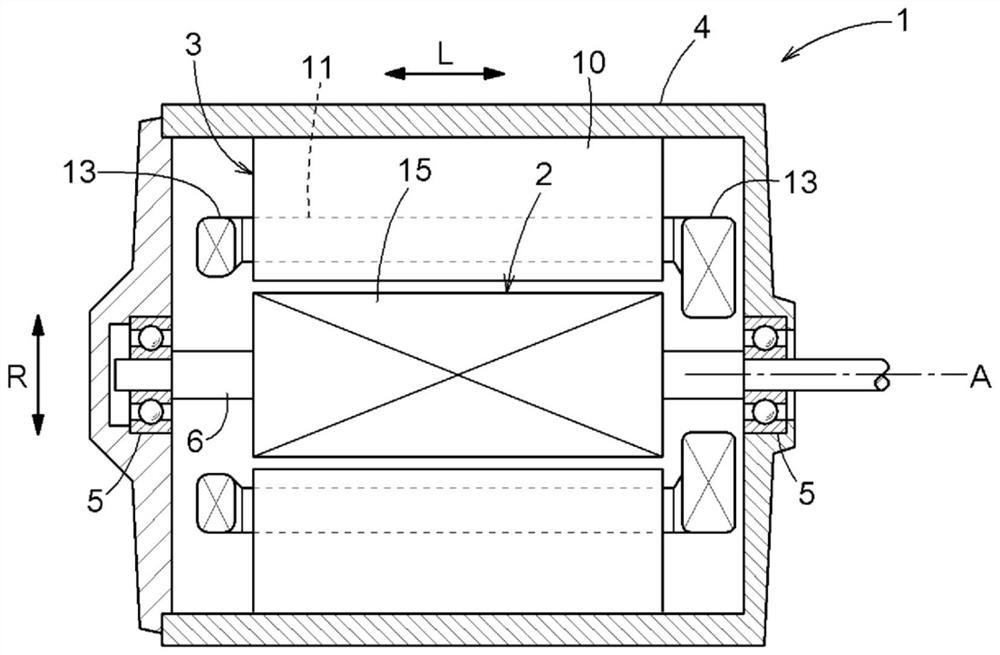
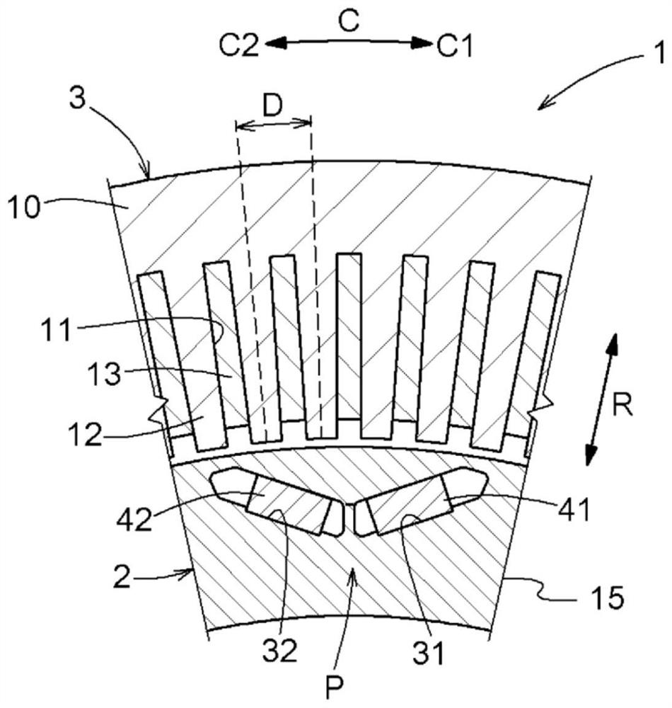
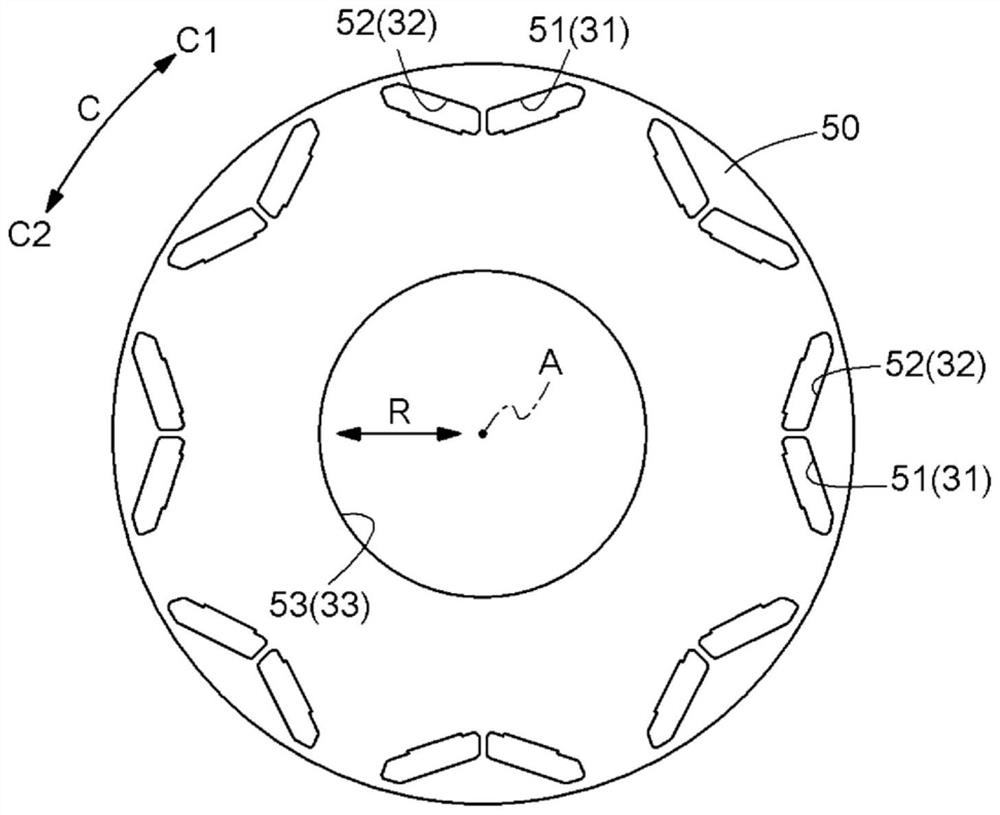
[0027] Embodiments of the rotor for a rotating electric machine and its manufacturing method will be described with reference to the drawings. In addition, in the following description, "axial direction L", "radial direction R", and "circumferential direction C" refer to the axis A (refer to figure 1 etc.) as the benchmark definition. The axis A is an imaginary axis, and the rotor 2 rotates around the axis A. And, if Figure 4 etc., let one side in the axial direction L be referred to as the "first axial side L1", and the other side in the axial direction L (the side opposite to the first axial side L1) be referred to as the "second axial side". side L2". In addition, one side in the circumferential direction C is referred to as "the first side C1 in the circumferential direction", and the other side in the circumferential direction C (the side opposite to the first side C1 in the circumferential direction) is referred to as "the second side C2 in the circumferential direct...


PUM


Abstract

The present invention relates to a rotor for a rotating electrical machine and a method for manufacturing the same. A rotor core (15) includes a laminated structure (20) formed by laminating a plurality of magnetic plates (50) in an axial direction L. In the laminated structure (20), a plurality of magnetic plates (50) are arranged so that their positions are shifted to one side in the circumferential direction C by a certain angle each time as they go to one side in the axial direction L. The magnet insertion holes (31, 32) are formed by a plurality of through holes communicating in the axial direction L over all of the plurality of magnetic plates (50). The permanent magnets (41, 42) are twisted around the axis A so as to be accommodated in the magnet insertion holes (31, 32) from the outside in the axial direction L.

Description

technical field [0001] The present invention relates to a rotor for a rotating electric machine including a rotor core and permanent magnets embedded in the rotor core, and a method for manufacturing the same. Background technique [0002] As an example of a rotor for a rotating electric machine, JP 2015-115985 A (Patent Document 1) discloses a rotor having a stepped skew structure. Specifically, the rotor core 1 of the rotor 3 of Patent Document 1 is divided into a plurality of blocks in the axial direction. Furthermore, the blocks are shifted in the circumferential direction to form a stepped skew. Adopting such a stepped skew structure can reduce cogging torque and torque ripple. [0003] However, in the structure described in Patent Document 1, the plurality of permanent magnets arranged in the axial direction are shifted in the circumferential direction in stages for each of the plurality of blocks, so that the effect of suppressing sudden changes in the magnetic flux...

Claims


Application Information

Patent Timeline
Patent Type & Authority Patents(China)
IPC IPC(8): H02K1/22H02K1/27
CPCH02K1/22H02K1/27H02K1/276H02K15/03H02K2213/03H02K2201/06H02K1/2766H02K29/03H02K15/024
Inventor 佐久间昌史津田哲平池本正幸
Owner AISIN AW CO LTD
Why Eureka
Try Eureka