A full-bridge rectifier and an adaptive adjustment device

A technology of self-adaptive adjustment and full-bridge rectification, which is applied to output power conversion devices, electrical components, etc., can solve the problems of large influence of comparators, difficult design, and reduced conduction voltage, and achieves high signal-to-noise rejection ratio, The effect of fast response signal-to-noise rejection ratio and improved efficiency

Active Publication Date: 2020-06-05
MAXIC TECHNOLOGY CORPORATION
View PDF3 Cites 0 Cited by
  • Summary
  • Abstract
  • Description
  • Claims
  • Application Information

AI Technical Summary

Problems solved by technology

[0007] However, just because the conduction resistance of the MOSFET is very small and the conduction voltage is reduced, the comparator's turn-off comparison threshold VTHOFF is usually between -1mV ~ -10mV, and if the input AC current frequency reaches 100KHz ~ 1MHz, this is require very fast comparator resolution and response
And because the bridge rectifier circuit usually flows a large current, the impact of noise on the comparator is also relatively large
[0008] For integrated circuit design, it is difficult to design a comparator that requires high resolution, high precision, fast response speed and high signal-to-noise rejection ratio at the same time

Method used


Image

  • A full-bridge rectifier and an adaptive adjustment device
  • A full-bridge rectifier and an adaptive adjustment device
  • A full-bridge rectifier and an adaptive adjustment device

Examples


Embodiment Construction

[0032] The technical solutions of the present invention will be described in further detail below with reference to the accompanying drawings and embodiments.

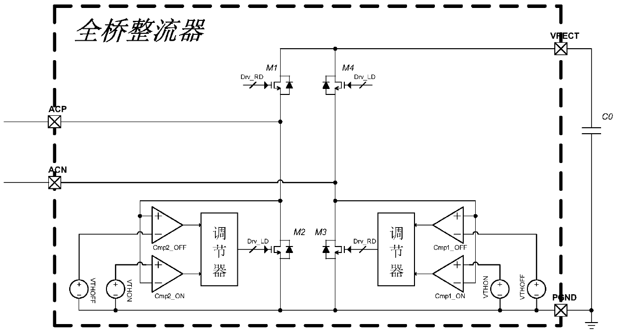
[0033] Figure 5 It is a schematic diagram of an adaptive adjustment device for a full-bridge rectifier realized according to an embodiment of the present invention.

[0034] Such as Figure 5 As shown, the adaptive adjustment circuit respectively delays the falling edges of Drv_LD and Drv_RD (td1 / td2), and the length of the delay can be automatically increased or decreased according to the information of Cmp1_ON and Cmp2_ON.

[0035] The basis for its increase or decrease is: when the gate control signals Drv_LD_td and Drv_RD_td of the MOSFET are 0—that is, after the MOSFET M2 or M3 is turned off, if the drain voltage of M2 or M3 drops to VTHON again, it means that the IAC current is still If there is no zero crossing, resulting in the conduction of the substrate diode of M2 or M3, then the delay time (td1 / td2) is i...


PUM


Abstract

The invention relates to a full bridge rectifier adaptive regulating circuit. The circuit includes a judgment circuit and a configurable delay circuit. The judgment circuit is connected to the configurable delay circuit. The judgment circuit is used for receiving driving voltage and a starting signal and outputting a control signal. The configurable delay circuit is used for receiving the controlsignal and the driving voltage and outputting delayed driving voltage. The turn-off the four MOSFETs in a full bridge rectifier can be accurately controlled through the adaptive regulating circuit ofthe invention, thereby improving the efficiency of the full bridge rectifier.

Description

technical field [0001] The invention relates to a full-bridge rectifier, in particular to an adaptive adjustment device for a full-bridge rectifier. Background technique [0002] A full-bridge rectifier is a commonly used circuit in power management, and its main function is to convert the input AC voltage into DC voltage. Such as figure 1 As shown, when the input AC current IAC is positive, the diodes D1 and D3 are turned on to charge the output capacitor C0; when the input AC current IAC is negative, the diodes D2 and D4 are turned on to charge the output capacitor C0. Since the diodes have a certain turn-on voltage threshold, the 4 diodes will be replaced by 4 MOSFETs, namely M1, M2, M3 and M4 in high current applications. [0003] Such as figure 2 As shown, since the diode is naturally conducting, no special circuit control is required for the diode. But in order to make the conduction behavior of the four MOSFETs similar to diodes, a comparator is needed to detect ...

Claims


Application Information

Patent Timeline
Patent Type & Authority Patents(China)
IPC IPC(8): H02M1/088
CPCH02M1/088
Inventor 郭越勇刘柳胜程宝洪
Owner MAXIC TECHNOLOGY CORPORATION
Why Eureka
Try Eureka