
Heat dissipation device capable of dissipating heat in partitioned mode and mainboard with heat dissipation device

A technology of cooling device and motherboard, applied in the direction of digital processing power distribution, instruments, electrical digital data processing, etc., can solve problems such as reducing operating performance, affecting motherboard performance, central processing unit and electronic parts loss and so on

Pending Publication Date: 2019-07-02
GIGA BYTE TECH CO LTD
View PDF7 Cites 1 Cited by
  • Summary
  • Abstract
  • Description
  • Claims
  • Application Information

AI Technical Summary

Problems solved by technology

[0003] However, regarding the operating performance and stability of the computer, the main key lies in the operation of the main board, central processing unit and electronic components. During the operation, a large amount of heat energy will be generated. In severe cases, it will be accumulated inside the main unit and cannot be easily dissipated outward, making the central processing unit Overheating and loss of devices and electronic components, thus reducing operating performance
[0004] For electronic components, such as power supply components, a large amount of heat energy is generated during operation. Generally, metal heat sinks and heat conduction media are used to conduct heat through contact with power supply components, and conduct heat to the heat sink to achieve the effect of heat dissipation. , whether there is air flow in the surrounding environment of the heat sink will affect the efficiency of heat dissipation, and also affect the performance of the motherboard

Method used


Image

  • Heat dissipation device capable of dissipating heat in partitioned mode and mainboard with heat dissipation device
  • Heat dissipation device capable of dissipating heat in partitioned mode and mainboard with heat dissipation device
  • Heat dissipation device capable of dissipating heat in partitioned mode and mainboard with heat dissipation device

Examples


Embodiment Construction

[0043] The technical solution of the present invention will be described in detail below in conjunction with the accompanying drawings and specific embodiments to further understand the purpose, solution and effect of the present invention, but it is not intended to limit the scope of protection of the appended claims of the present invention.

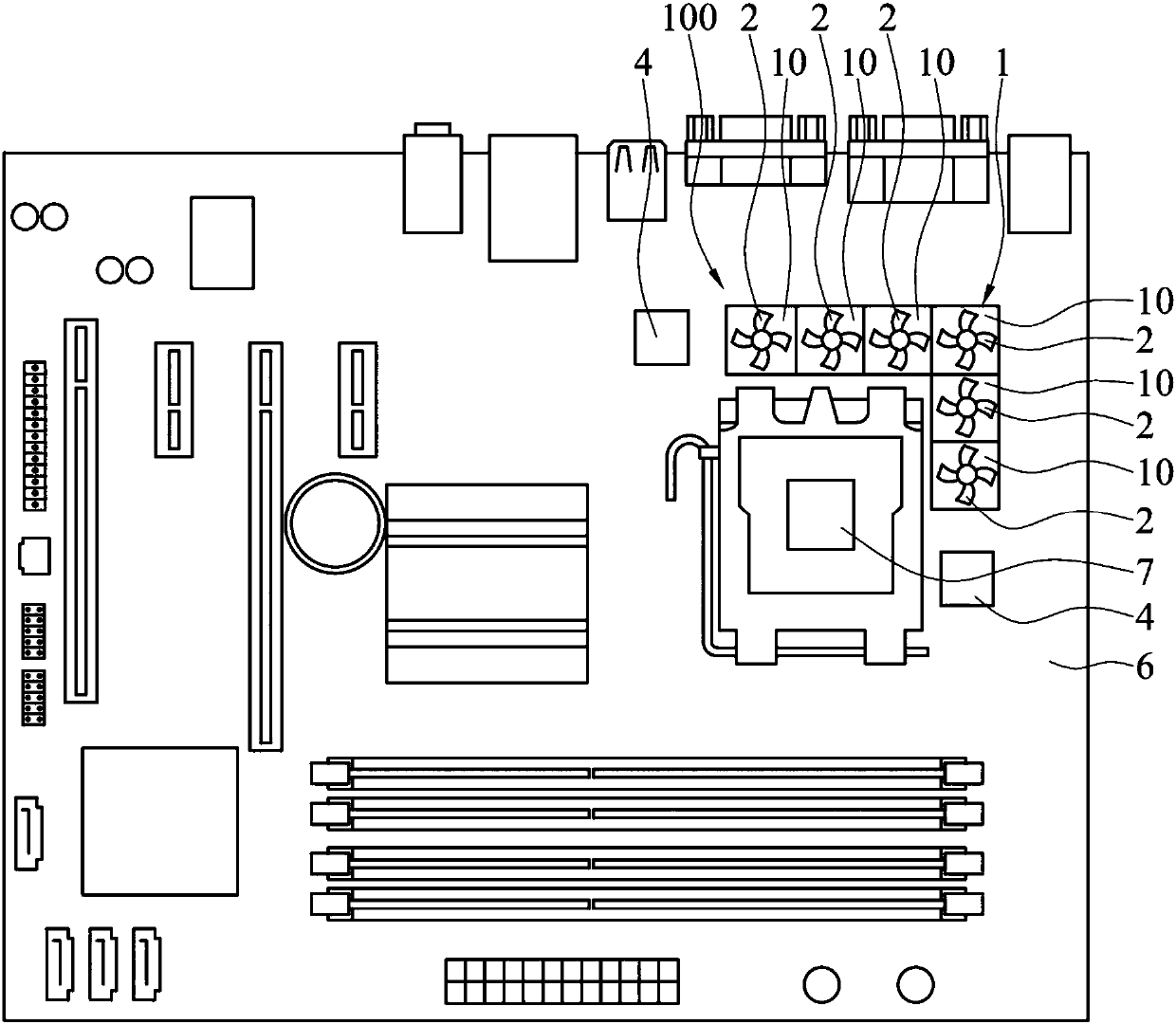
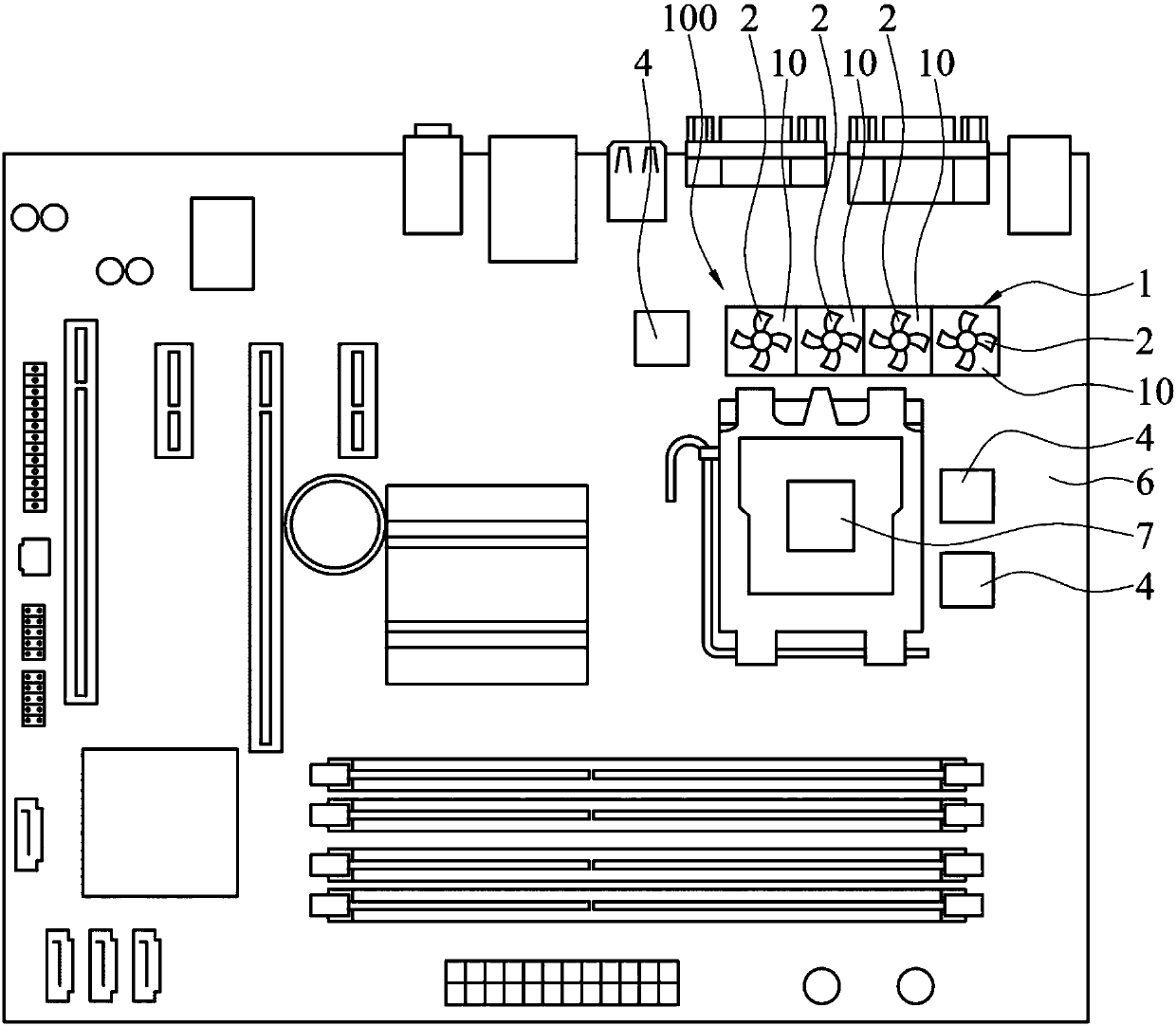
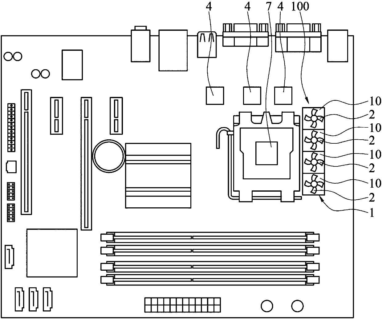
[0044] see Figure 1A to Figure 1C , are respectively schematic diagrams of an embodiment of the installation mode of the radiator of the present invention. The heat dissipation device 100 can be used to dissipate heat from a plurality of electronic components 4 . The heat dissipation device 100 includes a heat sink 1 , a plurality of fan modules 2 and a control circuit 3 . The heat sink 1 can conduct heat to each electronic component 4 . exist Figure 1A to Figure 1C In the shown embodiment, the upper surface of the heat sink 1 is divided into a plurality of heat dissipation areas 10, and each heat dissipation area 10 is used to co...


PUM


Abstract

The invention discloses a heat dissipation device capable of achieving partition heat dissipation and a mainboard with the heat dissipation device, and the heat dissipation device capable of achievingpartition heat dissipation is used for conducting heat dissipation on a plurality of electronic parts and comprises a heat dissipation device, a plurality of fan modules and a control circuit. The radiator is provided with a plurality of radiating areas, and each radiating area is used for conducting heat on at least one electronic part. The plurality of fan modules are arranged on the radiator,and each radiating area is at least correspondingly provided with one fan module. The control circuit is in signal connection with the electronic part and the fan module and detects the operation state of the electronic part, and at least one fan module in the heat dissipation area is controlled to act correspondingly to the operation state of the electronic part. The invention also provides a mainboard with the heat dissipation device.

Description

technical field [0001] A heat dissipation device, especially a heat dissipation device with multiple heat dissipation areas capable of dissipating heat in different regions. Background technique [0002] With the rapid development of science and technology, the application level of computers is becoming wider and wider, and people's demand for computers is also getting higher and higher. And for the quality of the computer, the emphasis is on high performance and good stability. [0003] However, regarding the operating performance and stability of the computer, the main key lies in the operation of the main board, central processing unit and electronic components. During the operation, a large amount of heat energy will be generated. In severe cases, it will be accumulated inside the main unit and cannot be easily dissipated outward, making the central processing unit Overheating and loss of devices and electronic components, thus reducing operating performance. [0004] ...

Claims


Application Information

Patent Timeline
IPC IPC(8): G06F1/20G06F1/18
CPCG06F1/183G06F1/20
Inventor 谌宏政廖哲贤
Owner GIGA BYTE TECH CO LTD
Learn More