Method for manufacturing packing material of optical member

A technology of optical components and manufacturing methods, which is applied to optical elements, optics, nonlinear optics, etc., can solve the problems of poor handling of optical components, biting air bubbles, etc., and achieve good handling effects

Active Publication Date: 2019-07-02
NITTO DENKO CORP
View PDF7 Cites 0 Cited by
  • Summary
  • Abstract
  • Description
  • Claims
  • Application Information

AI Technical Summary

Problems solved by technology

), there is a problem that the handleability of the optical member is deteriorated, or bubbles are caught between the optical member and the unit substrate.

Method used


Image

  • Method for manufacturing packing material of optical member
  • Method for manufacturing packing material of optical member

Examples


Embodiment 1

[0094]

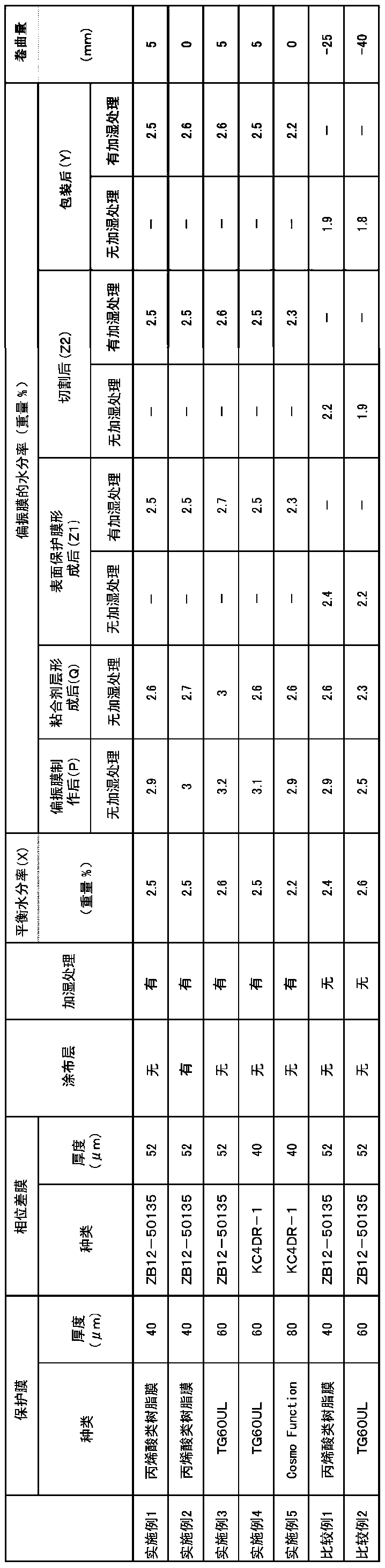
[0095] A corona-treated protective film and a phase difference film (manufactured by ZEON Corporation, trade name: ZB12-50135, thickness: 52 μm) were used on the easily-adhesive surface of an acrylic resin film having a lactone ring structure with a thickness of 40 μm. On the bonding surface, the above-mentioned ultraviolet curable adhesive was applied so that the cured thickness became 0.7 μm, and they were combined with a polarizing plate (manufactured by Kuraray Co., Ltd., trade name: PS4500, thickness: 45 μm) with a roll mill. face fit. Thereafter, ultraviolet rays are irradiated to cure the adhesive to produce a polarizing film. Then, when the equilibrium moisture content of the produced polarizing film was measured by the following method, the equilibrium moisture content X in the atmosphere of temperature 20 degreeC and relative humidity 55 %Rh was 2.5 weight%.

[0096] (Measurement of Equilibrium Moisture Content X of Polarizing Film)

[0097] Three sample...

Embodiment 2~5、 comparative example 1~2

[0136] In Example 1, as shown in Table 1, the type and thickness of the protective film, the type and thickness of the retardation film, and the presence or absence of humidification treatment were changed, and an optical member was produced in the same manner as in Example 1, And pack it. Moreover, the moisture content of each polarizing film was measured similarly to Example 1.

[0137] In addition, the coating layer of Example 2 was formed by the following method.

[0138] Prepare 50 parts by weight of ultraviolet curable urethane acrylate resin (manufactured by Nippon Synthetic Chemical Industry Co., Ltd., trade name "UV1700B", solid content 100%), and a multifunctional acrylate mainly composed of pentaerythritol triacrylate (Osaka Organic Chemical Industry Co., Ltd. product, brand name "VISCOAT #300", solid content 100%) 50 parts by weight. With respect to 100 parts by weight of the resin solid content of the above resin, copolymerized particles of acrylic acid (Japanes...


PUM

PropertyMeasurementUnit
thicknessaaaaaaaaaa
thicknessaaaaaaaaaa
thicknessaaaaaaaaaa

Abstract

An object of the present invention is to provide a method for manufacturing a package for an optical member in which at least an adhesive layer and a surface protective film are provided on a polarizing film, the package being less likely to curl when the optical member is attached to a cell substrate such as a liquid crystal cell. The method for manufacturing a package for an optical member according to the present invention is characterized by comprising: a step A of providing a protective film on one side or both sides of a polarizing plate via an adhesive layer to produce a polarizing film; a step B of at least arranging an adhesive layer and a surface protective film on the polarizing film to manufacture an optical component; and a step C of packaging the optical member, wherein whenthe equilibrium moisture content of the polarizing film in the optical member from the time when the package is unpacked to the time when the optical member is bonded to the unit substrate is X% by weight, the moisture content Y% by weight of the polarizing film in the optical member is adjusted so that the moisture content Y% by weight is not less than the equilibrium moisture content X% by weight in the step C.

Description

technical field [0001] The present invention relates to a method of manufacturing an optical component package. The above-mentioned optical member can form an image display device such as a liquid crystal display device (LCD) or an organic EL display device. Background technique [0002] In liquid crystal display devices and the like, it is essential to arrange polarizing elements on both sides of the liquid crystal cell depending on the image forming method, and generally a polarizing film is attached. In adhering the above-mentioned polarizing film to a liquid crystal cell, an adhesive is generally used. Moreover, in order to reduce the loss of light about the adhesion|attachment of a polarizing film and a liquid crystal cell, each material is normally brought into close contact using an adhesive. In such a case, since there are advantages such as fixing the polarizing film without a drying process, a polarizer with an adhesive layer in which the adhesive is previously p...

Claims


Application Information

Patent Timeline
Patent Type & Authority Applications(China)
IPC IPC(8): G02B5/30G02B1/14G02F1/1335
CPCG02B5/30G02B1/14G02F1/133528G02B1/10G02B5/3025B32B7/12B32B2307/42
Inventor 村山俊介中原步梦中田美惠
Owner NITTO DENKO CORP
Why Eureka
Try Eureka