Disc brake for a utility vehicle, and brake pad set

A technology of disc brakes and brake linings, applied in the direction of brake types, axial brakes, brake components, etc., can solve problems such as incompatibility

Active Publication Date: 2019-06-28
KNORR-BREMSE SYST FUER NUTZFAHRZEUGE GMBH
View PDF9 Cites 0 Cited by
  • Summary
  • Abstract
  • Description
  • Claims
  • Application Information

AI Technical Summary

Problems solved by technology

The floating brake caliper is suitable for passenger cars, but not for commercial vehicles

Method used


Image

  • Disc brake for a utility vehicle, and brake pad set
  • Disc brake for a utility vehicle, and brake pad set
  • Disc brake for a utility vehicle, and brake pad set

Examples


Embodiment Construction

[0096] The terms "upper", "lower", "left", "right" relate to the corresponding arrangement in the figures.

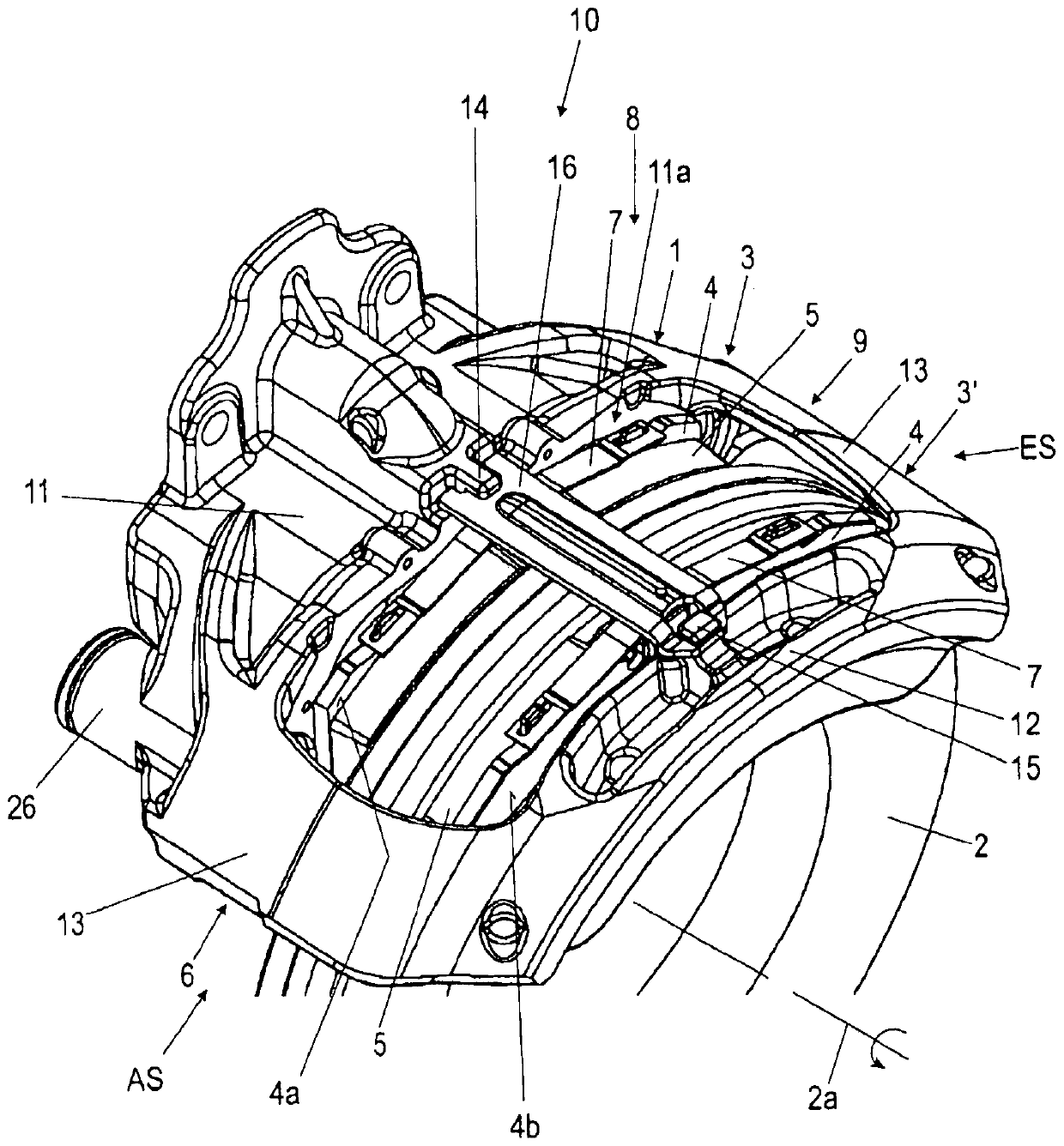
[0097] The “upper side” and the “lower side” of the brake lining 3 , 3 ′ or of the lining support plate 4 always refer to the installation situation of the respective brake lining 3 , 3 ′. In this case, the lower side of the respective brake lining 3 , 3 ′ is closer in the radial direction to the brake disk axis of rotation 2 a of the brake disk 2 than the upper side of the brake lining 3 , 3 ′.

[0098] The term “transverse axis” of the brake lining 3 , 3 ′ refers to an imaginary axis which, in the installed state of the brake lining 3 , 3 ′, extends radially to the axis of rotation 2 a of the brake disk. The “longitudinal axis” of the brake linings 3 , 3 ′ thus extends perpendicularly to said transverse axis and tangentially to the brake disc 2 .

[0099] figure 1 A schematic perspective view of an exemplary embodiment of a disk brake 10 according to the invention w...


PUM


Abstract

The invention relates to a disc brake for a utility vehicle, comprising a brake caliper which extends over the brake disc, is designed as a sliding caliper, is secured to a stationary brake carrier (6), and has a central opening over the brake disc. The disc brake also comprises two brake pads (3, 3') which are arranged in the brake caliper and can be moved in opposite directions, and which each have a lining carrier plate (4) and a friction lining (5) secured thereon. An action-side or application-side brake pad (3) can be pressed against the brake disc by means of an application device via at least one brake piston. The disc brake also comprises at least one return device (8), by means of which the brake pads (3, 3') can be returned after a movement caused by a braking process and aftera release of the brakes. The disc brake is designed such that the return device (8) has at least one return element (17, 18) which is attached to a brake pad (3, 3') and which is arranged between saidbrake pad (3, 3') and a stationary reference, and which exerts a return force on the brake pad (3, 3'). The invention also relates to a corresponding brake pad set.

Description

technical field [0001] The invention relates to a disc brake for a commercial vehicle according to the preamble of claim 1 . The invention also relates to a brake lining set. Background technique [0002] In disc brakes of the same type also known as sliding caliper brakes (or floating caliper brakes), braking is performed by means of a brake application device (which can be actuated pneumatically or electrically) In this case, the brake lining on the active side is pressed against the brake disc on the vehicle side. During the further course of the braking process, the brake caliper is moved against the brake application direction of the brake pad on the active side with reference to the brake disc, while simultaneously entraining and pressing the brake pad on the opposite reactive side onto the other side of the brake disc. [0003] In known disc brakes, after the brake is released, the brake caliper remains in a position in which the brake pads, at least the brake pads...

Claims


Application Information

Patent Timeline
Patent Type & Authority Applications(China)
IPC IPC(8): F16D55/226F16D65/092F16D65/097
CPCF16D55/226F16D65/092F16D65/0972F16D2055/0029F16D2065/1396F16D2127/02
Inventor M·莫尔纳I·内斯姆亚诺维奇M·豪泽C·布兰德尔M·海因德尔M·普莱恩廷格
Owner KNORR-BREMSE SYST FUER NUTZFAHRZEUGE GMBH
Why Eureka
Try Eureka