Post-cast belt supporting-free structure and post-cast belt construction method

A technology for supporting structures and post-casting belts, which is used in infrastructure engineering, underwater structures, artificial islands, etc., can solve the problems of inability to clean up debris in post-casting belts, waste of materials, time-consuming and labor-intensive, and avoid secondary erection. The process of the support frame, the effect of improving the construction efficiency and the simple process

Pending Publication Date: 2019-06-28
NINGBO DONGXIN CONSTR
View PDF0 Cites 2 Cited by
  • Summary
  • Abstract
  • Description
  • Claims
  • Application Information

AI Technical Summary

Problems solved by technology

[0003] In the construction of the existing post-cast belt, according to the technical requirements of the post-cast belt, it is necessary to complete the internal shrinkage of the structure after the final setting of the first poured concrete for a certain period of time, that is, the internal shrinkage of the structure is completed, and the concrete strength reaches the standard, and the debris in the post-cast belt must be cleaned. , the post-cast concrete is allowed to be poured. The problem with this construction method is that due to the limitation of the construction period, when the post-cast tape is poured, the support frame used in the cast-in-place often needs to be removed. Otherwise, the sundries in the post-cast tape will It cannot be cleaned, and the support frame can only be erected twice to solve the support problem of the formwork, which not only wastes materials, but also takes time and effort

Method used


Image

  • Post-cast belt supporting-free structure and post-cast belt construction method
  • Post-cast belt supporting-free structure and post-cast belt construction method
  • Post-cast belt supporting-free structure and post-cast belt construction method

Examples


Embodiment Construction

[0025] In order to make the technical means, creative features, goals and effects achieved by the present invention easy to understand, the following embodiments are combined with the accompanying drawings to elaborate on the present invention.

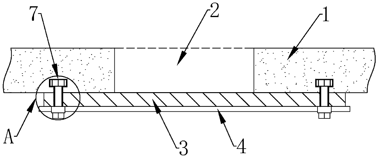
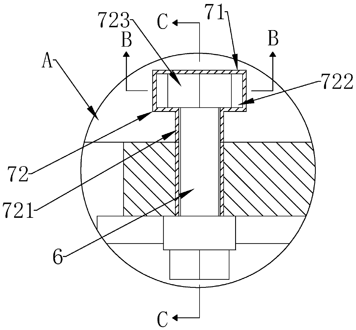
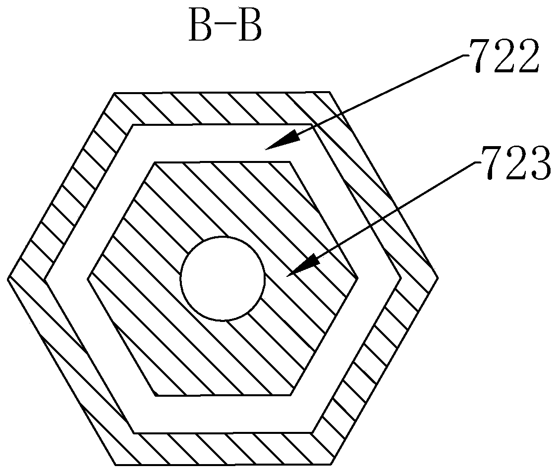
[0026] Please combine Figure 1 to Figure 4 , shows a support-free structure with post-casting belt 2, including a pre-cast concrete layer 1, a post-casting belt 2, a bottom formwork 3, a load-bearing steel pipe 4, a mountain-shaped card 5 and bolts 6, and the bottom formwork 3 is pre-embedded The parts 7 and the bolts 6 are installed and fixed under the first poured concrete layer 1, and poured between the two sections of the first poured concrete layer 1 to form the post-cast belt 2. Specifically, the embedded parts are set in the two sections of the first poured concrete layer 1 7. Correspondingly, through holes 31 matching the embedded parts 7 are provided at both ends of the bottom formwork 3. In order to enhance the bearing stre...


PUM


Abstract

The invention discloses a post-cast belt supporting-free structure and a post-cast belt construction method. The post-cast belt supporting-free structure comprises pre-cast concrete layers, a bottom formwork and a force bearing steel pipe, embedded parts are arranged in the two segments of pre-cast concrete layers respectively, and each embedded part comprises an embedded hole formed in the corresponding pre-cast concrete layer and an anchoring part arranged in the embedded hole and used for screwing a bolt; the bottom formwork is arranged below the pre-cast concrete layers, the force bearingsteel pipe is arranged below the bottom formwork, the bottom formwork and the force bearing steel pipe are fixed to the pre-cast concrete layers through an E-shaped clamp and a bolt, and concrete is poured between the two segments of pre-cast concrete layers to form a post-cast belt. According to the post-cast belt supporting-free structure, the bottom formwork is fixed by arranging the embedded parts to pour the post-cast belt, the complex mode is omitted that in the prior art, a supporting rack is erected below the bottom formwork for the second time, and the supporting-free mode has the advantages of being simple in structure, capable of saving materials and labor and reducing workload and good in formation quality.

Description

technical field [0001] The invention relates to the technical field of building construction, in particular to a post-cast belt support-free structure and a post-cast belt construction method. Background technique [0002] In the construction of building concrete structures, to prevent harmful cracks that may occur in the cast-in-place reinforced concrete structures due to uneven shrinkage or uneven settlement, according to the design requirements, temporary construction shall be reserved at the corresponding positions of the foundation floor, walls, beams and upper floors. The structure is divided into several parts temporarily, and the construction joint concrete is poured after a certain period of time after the internal contraction of the components, and the area that connects the structure into a whole is the post-casting belt. [0003] In the construction of the existing post-cast belt, according to the technical requirements of the post-cast belt, it is necessary to c...

Claims


Application Information

Patent Timeline
Patent Type & Authority Applications(China)
IPC IPC(8): E02D29/16E04G13/00
Inventor 陈小俊陈肇星
Owner NINGBO DONGXIN CONSTR
Why Eureka
Try Eureka