
Spray head structure for three-dimensional printing

A technology of three-dimensional printing and nozzles, which is applied in coating devices, manufacturing auxiliary devices, and processing data acquisition/processing. It can solve the problems of low printing accuracy, difficult processing, and high printing temperature, and achieve high printing efficiency and printing speed. Fast, high-precision printing effect

Inactive Publication Date: 2019-06-28
广州造维科技有限公司
View PDF6 Cites 0 Cited by
  • Summary
  • Abstract
  • Description
  • Claims
  • Application Information

AI Technical Summary

Problems solved by technology

[0003] At present, 3D printing technology is meeting people's personalized needs. If mechanical processing is used to complete the product manufacturing, the processing is difficult, the processing cycle is long, and the cost is expensive. Through 3D printers, people can print personalized products according to their own ideas. However, existing 3D printers, especially desktop 3D printers, vibrate significantly during the working process, especially at the printing nozzle, resulting in rough products, low printing accuracy, and high or low printing temperature, which makes printing not smooth The nozzle is prone to clogging, which affects the printing speed, makes the 3D printing efficiency low, and cannot meet people's needs. Therefore, it is urgent to improve the 3D printing technology.

Method used


Image

  • Spray head structure for three-dimensional printing
  • Spray head structure for three-dimensional printing
  • Spray head structure for three-dimensional printing

Examples


Embodiment Construction

[0039] The implementation of the present invention will be illustrated by specific specific examples below, and those skilled in the art can easily understand other advantages and effects of the present invention from the contents disclosed in this specification.

[0040] It should be noted that the structures, proportions, sizes, etc. shown in the drawings of this specification are only used to match the content disclosed in the specification, for those who are familiar with this technology to understand and read, and are not used to limit the conditions for the implementation of the present invention , so it has no technical substantive meaning, and any modification of structure, change of proportional relationship or adjustment of size shall still fall within the scope of the disclosure of the present invention without affecting the functions and objectives of the present invention. within the range covered by the technical content. At the same time, terms such as "upper", ...


PUM

PropertyMeasurementUnit
angleaaaaaaaaaa

Abstract

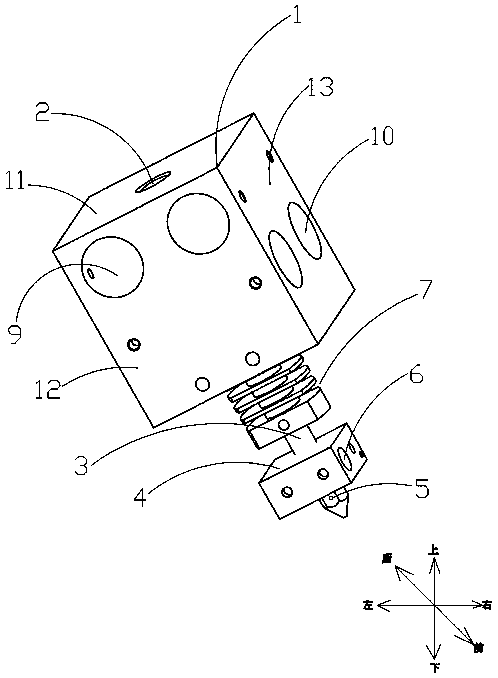
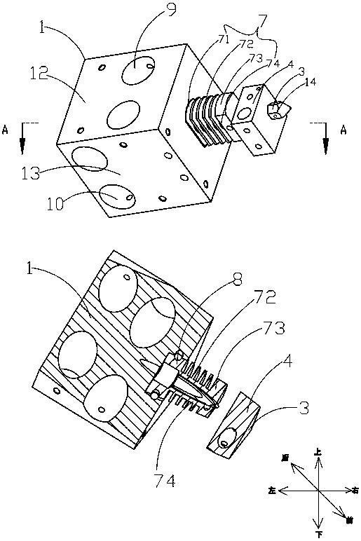
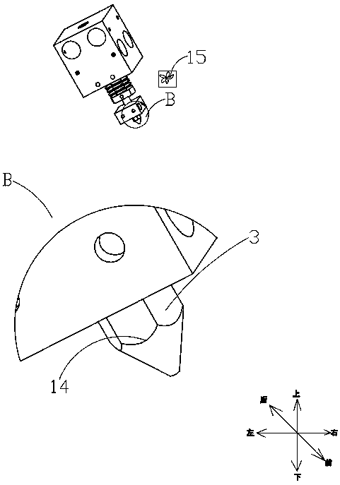
The invention provides a spray head structure for three-dimensional printing, belongs to the technical field of three-dimensional printing, and solves the problem that printing is not smooth due to incapability of controlling printing temperature. The spray head structure for three-dimensional printing comprises a fixed seat, a first through hole is formed in the surface of the fixed seat in an axial direction, a nozzle is made of high-precision alloy, one end of the nozzle is connected with one end of the through hole, a heater is connected to the position, close to the other end of the nozzle, of the nozzle, the spray head structure further comprises a temperature sensor arranged on the nozzle and a controller arranged on the heater, and the controller is electrically connected with thetemperature sensor and the controller. According to the spray head structure for three-dimensional printing, the heater is used for controlling the heater to heat the nozzle through the temperature sensor arranged on the nozzle and the controller arranged on the heater, so that the blockage caused by too high temperature or too low temperature is avoided, the spray head structure further has the advantages of being smooth, high in printing speed and high in printing efficiency; and meanwhile, the nozzle made of high-precision alloy is utilized, so that the advantages of being high in printingprecision and long in service life are achieved.

Description

technical field [0001] The invention relates to the technical field of three-dimensional printers, in particular to a nozzle structure for three-dimensional printing. Background technique [0002] With the development of science and technology, the modern manufacturing industry has developed rapidly, and 3D printing technology has followed, which continuously meets the needs of enterprises for various shapes and structures and reduces production costs. For example, in the product development stage, the model is processed by a 3D printer. Printing can greatly reduce the cost of tooling. [0003] At present, 3D printing technology is meeting people's personalized needs. If mechanical processing is used to complete the product manufacturing, the processing is difficult, the processing cycle is long, and the cost is expensive. Through 3D printers, people can print personalized products according to their own ideas. However, existing 3D printers, especially desktop 3D printers, ...

Claims


Application Information

Patent Timeline
Patent Type & Authority Applications(China)
IPC IPC(8): B29C64/209B29C64/393B33Y30/00B33Y50/02
Inventor 林烁黎健新
Owner 广州造维科技有限公司
Learn More