
Waveguide filter blank body forming mold and its technology

A technology for waveguide filters and forming molds, which is applied in the direction of molds, forming indenters, ceramic forming machines, etc., and can solve problems such as blind holes that cannot be formed, cracks, and missing corners in finished embryos

Active Publication Date: 2020-02-14
苏州捷频电子科技有限公司
View PDF4 Cites 0 Cited by
  • Summary
  • Abstract
  • Description
  • Claims
  • Application Information

AI Technical Summary

Problems solved by technology

[0015] The technical problem to be solved by the present invention is to provide a waveguide filter blank body forming mold, which is used for dry pressing the ceramic dielectric waveguide filter blank body, so as to overcome the problems of missing corners, cracks and even breakage of the finished blank body, and the problems in the prior art The problem that blind holes cannot be formed on the opposite surfaces of the embryo body can greatly improve the yield of the formed embryo body

Method used


Image

  • Waveguide filter blank body forming mold and its technology
  • Waveguide filter blank body forming mold and its technology

Examples


Embodiment 1

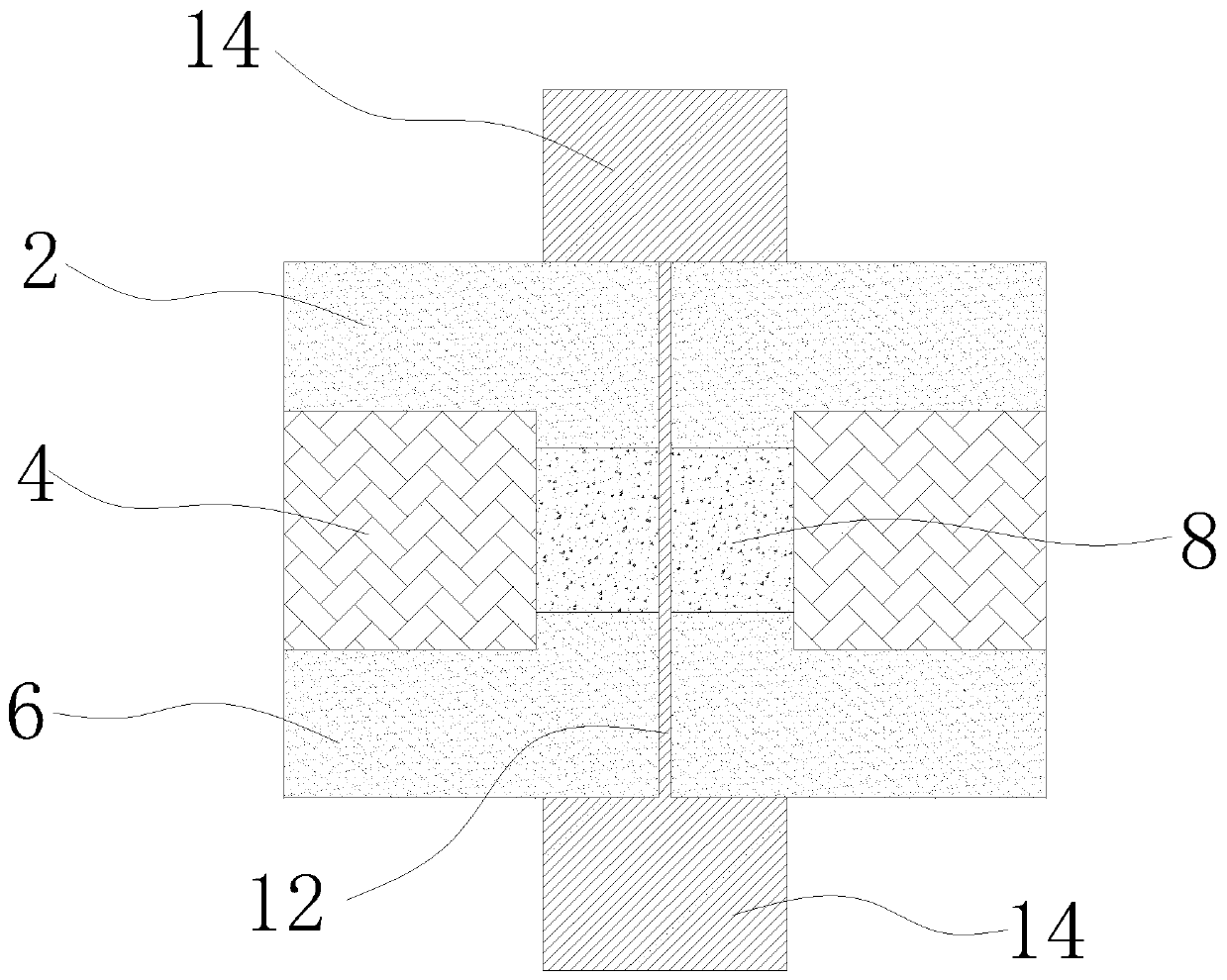
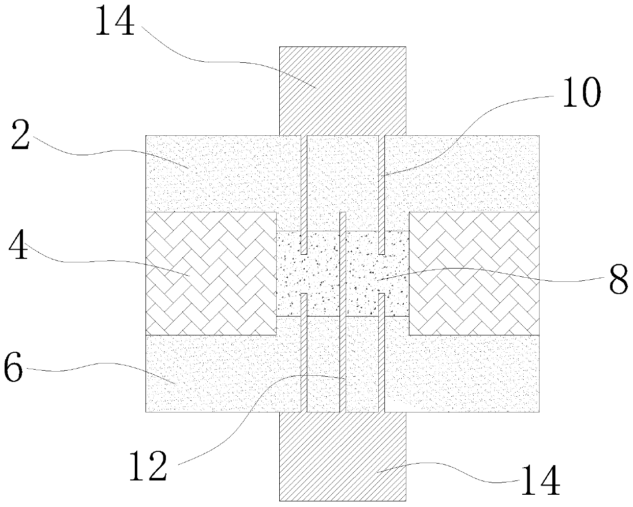
[0049] refer to figure 1 As shown, the present invention discloses a waveguide filter blank forming mold, comprising an upper mold 2, a middle mold 4, a lower mold 6, an upper mold mandrel 10 and a lower mold mandrel 12; the middle mold 4 has a mold cavity 8 , the above-mentioned mold cavity 8 is filled with powder for pressing and forming an embryo body; the middle mold 4 has an upper mold channel and a lower mold channel that are all communicated with the mold cavity 8, and the other end of the upper mold channel extends to the upper mold of the middle mold surface, the other end of the lower mold channel extends to the lower surface of the middle mold. Above-mentioned upper die 2 and lower die 6 are respectively arranged directly above and directly below middle die 4; The bottom is embedded in the middle mold 4 along the channel of the upper mold and pressurized to dry-press the powder in the mold cavity 8 into an embryo body. The above-mentioned lower mold mandrel 12 is ...

Embodiment 2

[0055] This embodiment discloses a waveguide filter blank forming process, which uses the blank forming mold of Embodiment 1 to physically dry press the waveguide filter blank. The initial state of the forming mold is: ①The top of the lower mold 6 is along the bottom The mold channel is embedded inside the middle mold 4 to block the above-mentioned mold cavity 8; ②The bottom of the upper mold 6 is located directly above the upper mold channel and does not touch the middle mold 4; ③The mandrel 12 of the lower mold fixed on the mandrel base 14 passes through Enter the lower mold 6; ④The upper mold mandrel 10 fixed on the mandrel base 14 penetrates the upper mold 2; ⑤The upper mold 2, the middle mold 4, the lower mold 6, the upper mold mandrel 10 and the lower mold mandrel 12 are connected to the driver, and can rise or fall independently under the drive of the driver; the steps of dry pressing the waveguide filter body based on the molding mold are as follows:

[0056] (1) Under...


PUM


Abstract

The invention discloses a forming mould for a waveguide filter green body. The forming mould comprises a middle mould, an upper mould, a lower mould and a lower mould core rod, and further comprises an upper mould core rod, wherein a mould cavity is arranged in the middle mould; and the upper mould and the lower mould are separately arranged above and below the middle mould. The forming mould is characterized in that after the lower mould core rod passes through the lower mould and extends into the mould cavity, one part of the lower mould core rod gets out of the mould cavity and extends intothe upper mould; the upper mould core rod passes through the upper mould and then extends into the mould cavity; and the middle mould, the upper mould, the lower mould, the upper mould core rod and the lower mould core rod are connected to a driver, and can independently ascend or descend under driving of the driver. The invention further discloses a forming process for the waveguide filter greenbody. The forming mould and process for the waveguide filter green body disclosed by the invention is used for dry-pressing and forming a ceramic medium waveguide filter green body, overcomes the problems that green body finished products have unfilled corners, cracks and even breakage, and the problem that blind holes cannot be formed in opposite two surfaces of the green body in the prior art,and can greatly increase the yield of the formed green body.

Description

technical field [0001] The present invention relates to the technical field of embryo body dry pressing, and relates to a molding process for dry pressing ceramic powder into an embryo body, in particular to a waveguide filter embryo body forming process, and also to a waveguide filter embryo body forming mold . Background technique [0002] The ceramic dielectric filter is to print the filter circuit on the ceramic body to realize the electrical performance of the filter, and the molding of the ceramic body is a very important process link. Different from the existing ceramic dielectric filter, the ceramic dielectric waveguide filter has a very obvious difference both in the size of the body and in the structure: the body of the existing ceramic dielectric filter is a cuboid structure, which penetrates the thickness of the cuboid ( Or height) has a row of through holes in the direction. The body of the ceramic dielectric waveguide filter is a cuboid structure, and there a...

Claims


Application Information

Patent Timeline
Patent Type & Authority Patents(China)
IPC IPC(8): B28B3/04B28B7/00B28B7/16
Inventor 刘亚东
Owner 苏州捷频电子科技有限公司
Learn More