
Inhaling type anesthesia device

An inhaled, centrally located technology, used in the medical field, can solve the problems of difficult control of anesthesia time, irritation of the respiratory tract, and difficulty in cavity organs, so as to ensure the patient's condition and operation, the control of the depth of anesthesia, and the ease of the depth of anesthesia. Effect

Inactive Publication Date: 2019-06-28
寇建敏
View PDF0 Cites 1 Cited by
  • Summary
  • Abstract
  • Description
  • Claims
  • Application Information

AI Technical Summary

Problems solved by technology

[0003] At present, when clinically anesthesizing patients, most of them use disposable syringes for multiple punctures to inject anesthetic drugs, which is troublesome, time-consuming and labor-intensive, and the anesthetic drugs diffuse slowly, which seriously affects the progress of the operation and increases the workload of medical staff; The injection needle is relatively straight. When anesthetizing the patient, it is easier to anesthetize the surface tissue, but it is very difficult for some cavity organs, which adds great difficulty to the medical staff;
[0004] The commonly used respiratory inhalation anesthesia often requires a doctor to operate, but the depth of anesthesia is not easy to control, it is irritating to the respiratory tract, the anesthesia time is not easy to control, and the recovery after anesthesia will affect the patient's condition and the operation, and will also bring many problems. Unstable factors

Method used

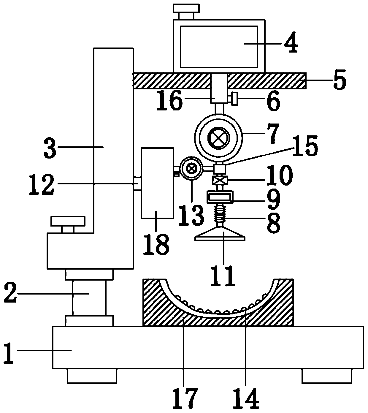
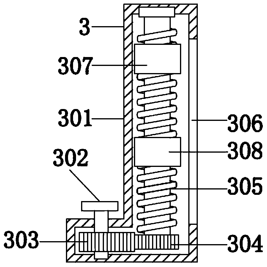
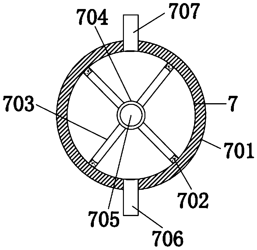

Image

  • Inhaling type anesthesia device
  • Inhaling type anesthesia device
  • Inhaling type anesthesia device

Examples


Embodiment Construction

[0021] The following will clearly and completely describe the technical solutions in the embodiments of the present invention with reference to the accompanying drawings in the embodiments of the present invention. Obviously, the described embodiments are only some, not all, embodiments of the present invention. Based on the embodiments of the present invention, all other embodiments obtained by persons of ordinary skill in the art without making creative efforts belong to the protection scope of the present invention.

[0022] see Figure 1-3 , the present invention provides a technical solution: an inhalation anesthesia device, comprising a base 1, a headrest 17 is clamped at the top center of the base 1, and a rubber pad 14 is attached to the upper surface of the headrest 17, The patient can be made more comfortable by the rubber pad 14, the top left side of the base 1 is welded with a strut 2, and the top of the strut 2 is fixedly equipped with a drive mechanism 3;

[002...


PUM


Abstract

The invention discloses an inhaling type anesthesia device which comprises a base. A headrest is clamped at the center of the top end of the base. A supporting rod is welded to the left side of the top end of the base. A driving mechanism is fixedly installed at the top end of the supporting rod. A first transverse plate and a second transverse plate are welded to the right side of a first threaded sleeve block and the right side of a second threaded sleeve block respectively. The right side of the first transverse plate and the right side of the second transverse plate both extend out of a slide groove. The top end of the first transverse plate is connected with an anesthesia gas tank through screws. The bottom end of the anesthesia gas tank is in interference fit with a conveying pipe. The bottom end of the conveying pipe extends out of the first transverse plate to be fixedly connected with a first conveying mechanism. The bottom end of the first conveying mechanism is fixedly provided with a two-way pipe. It is ensured that the ratio of anesthesia gas to oxygen is always kept correct, the anesthesia depth is easy to control, the irritation is prevented from being generated to the respiratory tract, the anesthesia effect is better, the patient conditions and surgery are ensured, and the use safety is improved.

Description

technical field [0001] The invention relates to the field of medical technology, in particular to an inhalation anesthesia device. Background technique [0002] The meaning of anesthesia is to use drugs or other methods to temporarily deprive the patient of the whole or part of the sensation in order to achieve painless surgical treatment. Safety is a science that creates good conditions for surgery. Now, anesthesiology has become a specialized independent discipline in clinical medicine, mainly including clinical anesthesiology, emergency resuscitation medicine, intensive care monitoring therapy, pain diagnosis and treatment, and other related medicine and medicine. The study of its mechanism is a comprehensive subject that studies anesthesia, analgesia, emergency resuscitation and intensive care medicine; [0003] At present, when clinically anesthesizing patients, most of them use disposable syringes for multiple punctures to inject anesthetic drugs, which is troublesome...

Claims


Application Information

Patent Timeline
IPC IPC(8): A61M16/01
Inventor 寇建敏秦璐
Owner 寇建敏
Learn More