Position adjusting mechanism of punch press ejector plate

A technology of adjusting mechanism and ejector plate, applied in the direction of presses, manufacturing tools, etc., can solve the problems of large vibration, low precision, complex movable mold structure, etc., and achieve high production efficiency, high position adjustment precision, and reduced occupied volume. Effect

Inactive Publication Date: 2019-06-25
NINGBO BOXIN MACHINERY
View PDF0 Cites 0 Cited by
  • Summary
  • Abstract
  • Description
  • Claims
  • Application Information

AI Technical Summary

Problems solved by technology

[0003] During the punching process of the punching machine, according to the shape, thickness and material of the workpiece, the height of the mold needs to be adjusted to meet the needs of production. It is realized by adjusting the stroke of the movable mold, but this method makes the structure of the movable mold complex, with large vibration and low precision, so it is necessary to optimize a position adjustment mechanism for the punching plate of the punch press

Method used


Image

  • Position adjusting mechanism of punch press ejector plate
  • Position adjusting mechanism of punch press ejector plate
  • Position adjusting mechanism of punch press ejector plate

Examples


Embodiment

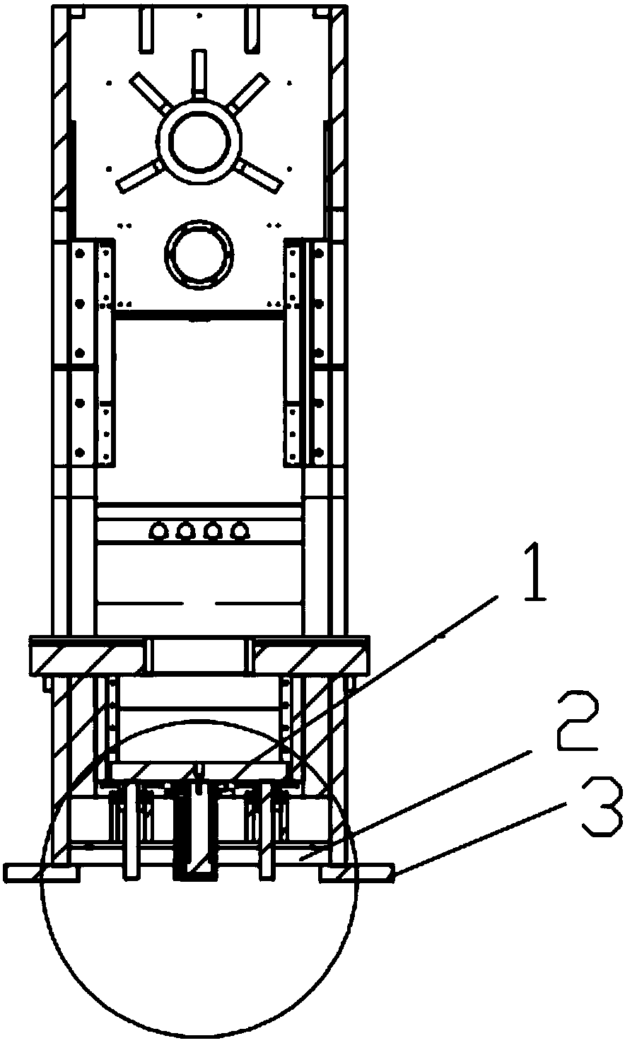
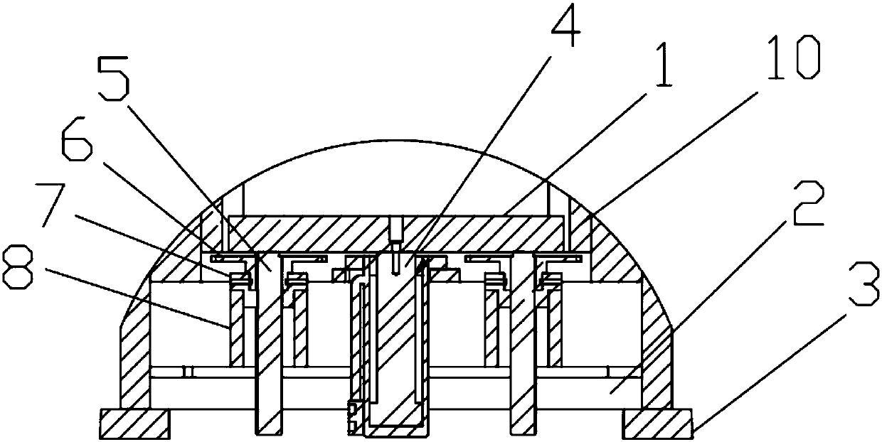
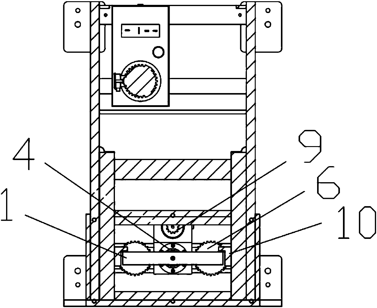
[0018] When in use, first open the oil cylinder 4, under the limit action of the guide plate 10, adjust the position of the ejector plate 1 through the piston rod of the oil cylinder 4, and adjust the distance between the ejector plate 1 and the punching die to adapt to the workpiece. Stamping needs, further, turn on the disc motor, drive the driving sprocket 9 at one end of the disc motor shaft to rotate, the driving sprocket 9 drives the driven sprocket 6 on both sides to rotate through the chain, and the driven sprocket 6 is on the bearing 7 Under the support, the screw rod 5 is rotated to move upwards. Further, the upper end of the screw rod 5 bears against the ejector plate 1. Under the support of the screw rod 5, the movable mold of the punching machine presses downward.


PUM


Abstract

The invention relates to a position adjusting mechanism of a punch press ejector plate. The position adjusting mechanism comprises a bottom plate arranged at the lower part of a machine frame of a punch press, an oil cylinder is vertically arranged in the middle of the bottom plate, and the ejector plate is fixedly connected to the upper end of a piston rod of the oil cylinder; two supporting blocks are symmetrically arranged between the bottom plate and the ejector plate, a bearing is fixedly arranged at the upper end of each supporting block, a driven chain wheel is arranged on the inner ring of each bearing, a screw rod is mounted on an inner thread of each driven chain wheel, and the upper ends of the screw rods abut against the lower end of the ejector plate; a driving chain wheel connected with the driven chain wheels through a chain is arranged behind the oil cylinder, and a disc type motor for driving the driving chain wheel to rotate is vertically arranged below the driving chain wheel. The position adjusting mechanism has the characteristics of being stable in structure, high in position adjusting precision, high in production efficiency and the like.

Description

technical field [0001] The invention relates to the technical field of punching machines, in particular to a position adjustment mechanism for a punching plate of a punching machine. Background technique [0002] A punching machine is a stamping press that can make blanking, punching, forming, deep drawing, trimming, fine blanking, shaping, riveting and extrusion parts through a mold, and is widely used in various fields. [0003] During the punching process of the punching machine, according to the shape, thickness and material of the workpiece, the height of the mold needs to be adjusted to meet the needs of production. It is realized by adjusting the stroke of the movable die, and this method makes the structure of the movable die complex, with large vibration and low precision, so it is necessary to optimize a position adjustment mechanism for the punching plate of the punch press. Contents of the invention [0004] The technical problem to be solved by the present in...

Claims


Application Information

Patent Timeline
Patent Type & Authority Applications(China)
IPC IPC(8): B30B15/00
Inventor 王梅张令菊林海龙
Owner NINGBO BOXIN MACHINERY
Why Eureka
Try Eureka