
Battery pack

A technology for battery packs and battery cells, applied to battery pack components, secondary batteries, circuits, etc., can solve problems such as heavy loads and dangers, and achieve the effect of suppressing fracture and reducing displacement

Active Publication Date: 2019-06-21
PANASONIC INTPROP MANAGEMENT CO LTD
View PDF7 Cites 1 Cited by
  • Summary
  • Abstract
  • Description
  • Claims
  • Application Information

AI Technical Summary

Problems solved by technology

As a result, a large load is also generated on the welded part, and it becomes very dangerous

Method used


Image

  • Battery pack
  • Battery pack
  • Battery pack

Examples


Embodiment approach 1

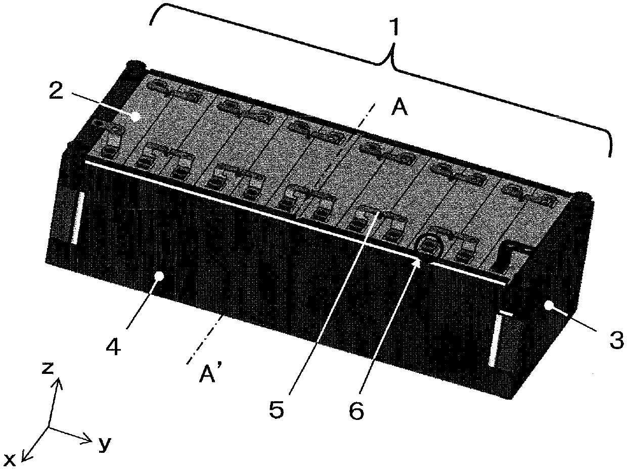
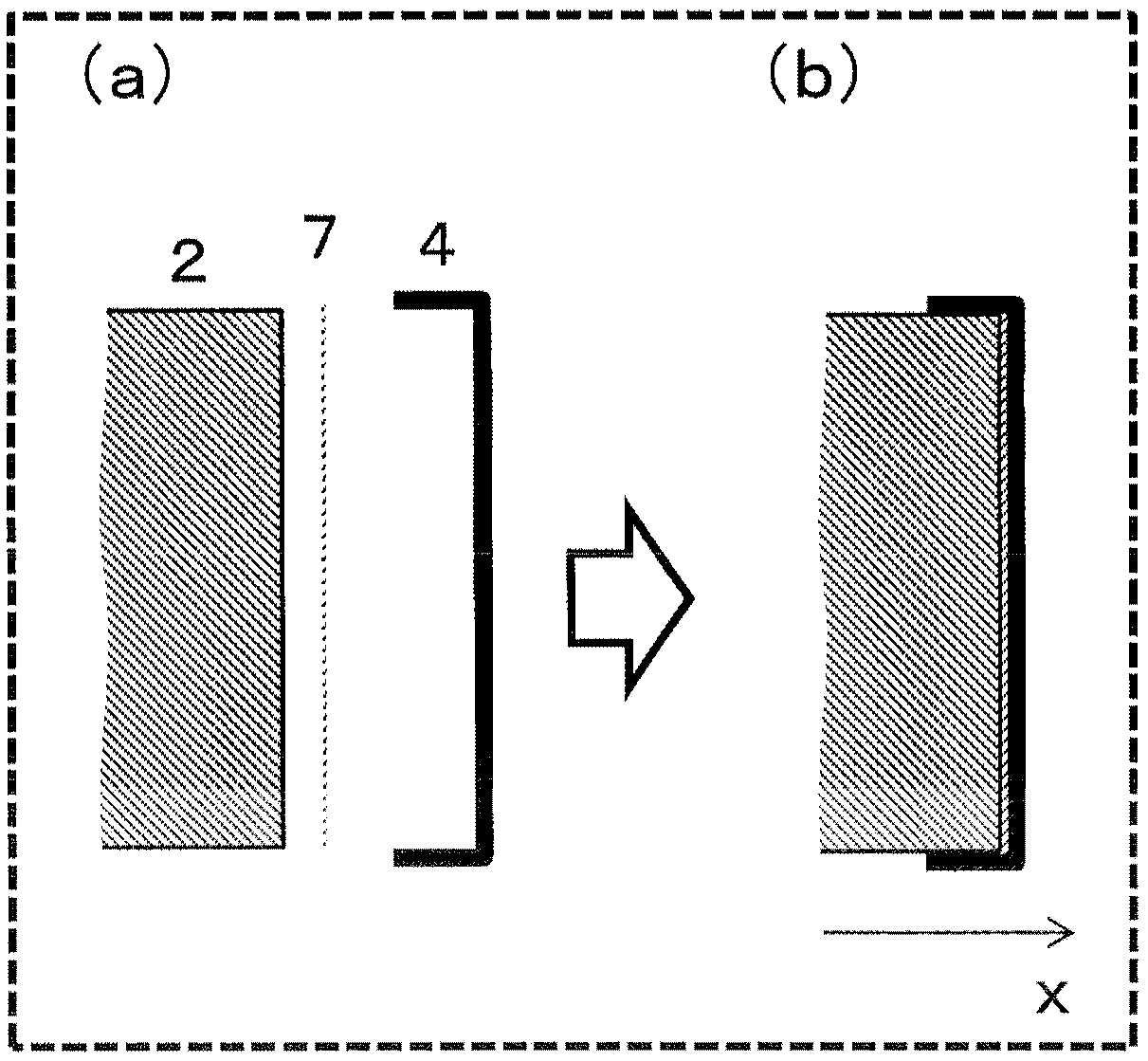
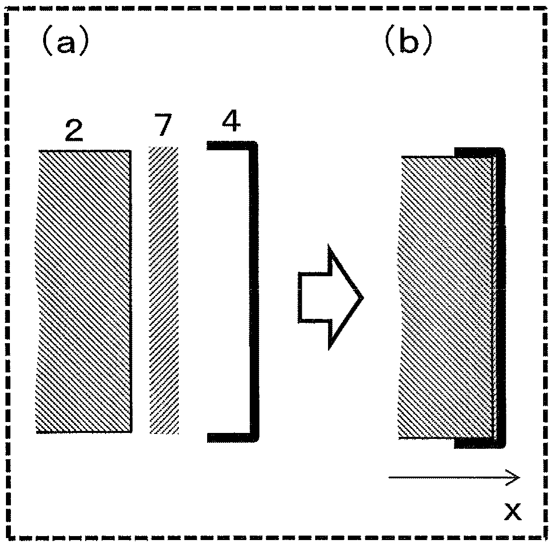
[0040] Figure 1A It is a perspective view showing the whole of the battery pack 1 according to Embodiment 1 of the present invention. Figure 1B (a) means Figure 1A An exploded view of the structure of the battery cell 2 , the thin insulator 7 and the connecting rod 4 between the battery cell 2 and the end plate 3 at one end of the battery pack 1 . Figure 1B (b) is after Figure 1A The broken line A-A' of the battery pack 1 and the section of the battery pack 1 perpendicular to the arrangement direction (y direction) only show the schematic cross-sectional view of the battery unit 2, the connecting rod 4 and the insulator 7 of (a). Figure 1C (a) means Figure 1A An exploded view of the structure of the battery cell 2 , the thick insulator 7 and the connecting rod 4 between the battery cell 2 and the end plate 3 at one end of the battery pack 1 . Figure 1C (b) is after Figure 1A The broken line A-A' of the battery pack 1 and the section of the battery pack 1 perpendi...

Embodiment approach 2

[0073] In Embodiment 1, the structure in which the compressed insulator 7 arranged between the battery cells 2 and the connecting rods 4 is interposed is adopted. In the battery pack according to Embodiment 2, the structure is different in that the assembled battery pack 1, the insulator 7 is bonded to one or both of the connecting rod 4 or the battery unit 2 . Since the insulator 7 is bonded to at least one of the connecting rod 4 or the battery cell 2, the displacement of the battery cell 2 when impacted in the alignment direction is smaller than that of the first embodiment in which only friction acts. Therefore, it is possible to further reduce the load on the welding portion acting between the electrode terminal 6 and the bus bar 5 .

[0074] In addition, for the case where the outer surface of the battery cell 2 is made of a metal material or the connecting rod 4 made of a metal material, by roughening the surface, the coefficient of friction can be increased, and a bett...


PUM

PropertyMeasurementUnit
compression ratioaaaaaaaaaa
dynamic friction coefficientaaaaaaaaaa

Abstract

The present invention provides a battery pack that suppresses breakage at a junction between a bus bar and an electrode. The battery pack includes: a plurality of battery cells in a line arranged in one direction as an arrangement direction; a pair of end plates configured to sandwich the plurality of battery cells in the line from both ends in the arrangement direction of the plurality of batterycells; a pair of binding bars configured to sandwich the plurality of battery cells from a direction perpendicular to the arrangement direction and to fasten the pair of end plates at both ends in the arrangement direction; and an insulator sandwiched in a gap between each of the binding bars and the battery cells, wherein the insulator having an initial thickness larger than a thickness of the gap before insertion into the gap is in a compressed state.

Description

technical field [0001] The present invention relates to a battery pack in which a plurality of battery cells are arranged in one direction. Background technique [0002] It is known that when a plurality of battery cells are arranged in series and the electrode terminals located at both ends of the adjacent battery cells are connected through a current collector called a bus bar in a conventional battery pack, laser welding of the electrode terminals and the bus bar is used. method (for example, refer to Patent Document 1). [0003] Figure 6 It is a schematic perspective view showing the overall structure of the conventional battery pack described in Patent Document 1 above. Figure 6 An overall view showing a conventional battery pack. In this figure, the battery pack 1 has a structure in which a plurality of battery cells 2 are arranged in series, and both ends of the battery cells 2 are sandwiched by end plates 3, and the end plates 3 are connected to each other by conn...

Claims


Application Information

Patent Timeline
Patent Type & Authority Applications(China)
IPC IPC(8): H01M2/10H01M2/20H01M2/34H01M50/209H01M50/264H01M50/293
CPCH01M10/0481Y02E60/10Y02P70/50H01M50/293H01M50/209H01M50/264
Inventor 江岛恒行
Owner PANASONIC INTPROP MANAGEMENT CO LTD
Learn More