
Detection method and device of optical component surface topography and subsurface defect information

A technology of subsurface defects and optical components, applied in the direction of using optical devices, optical testing flaws/defects, measuring devices, etc., can solve problems such as imperfect detection, and achieve the effects of high measurement capability, high measurement accuracy, and high measurement efficiency.

Active Publication Date: 2019-06-21
XIAN TECHNOLOGICAL UNIV
View PDF7 Cites 20 Cited by
  • Summary
  • Abstract
  • Description
  • Claims
  • Application Information

AI Technical Summary

Problems solved by technology

The traditional existing technology is not perfect for the detection of subsurface defects of optical components, such as the position and depth information of internal defects of components, etc.

Method used


Image

  • Detection method and device of optical component surface topography and subsurface defect information
  • Detection method and device of optical component surface topography and subsurface defect information
  • Detection method and device of optical component surface topography and subsurface defect information

Examples


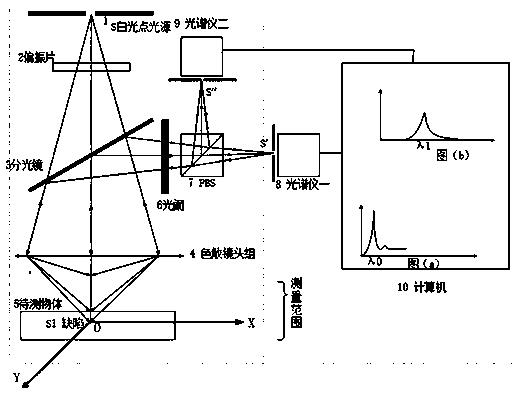
Embodiment Construction

[0026] In order to make the object, technical solution and advantages of the present invention clearer, the present invention will be further described in detail below in conjunction with the accompanying drawings and embodiments. It should be understood that the specific embodiments described here are only used to explain the present invention, not to limit the present invention.

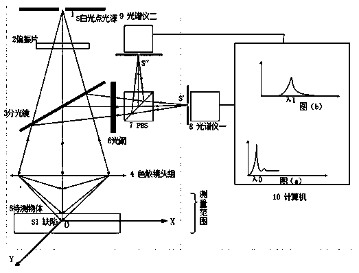
[0027] The steps of the detection method for the surface topography and subsurface defect depth information of the optical element are as follows:

[0028] Step 1: A beam of wide-spectrum polychromatic light is emitted from the light source through the small hole S, and after passing through the polarizer 2, the ordinary light source is converted into linearly polarized light with a vibration direction perpendicular to the XOY plane, and irradiated on the dispersion lens group;

[0029] Step 2: The light passes through the dispersive lens to undergo spectral dispersion, thereby dispersing the white...


PUM


Abstract

The invention relates to a detection method and device of optical component surface topography and subsurface defect information. The method comprises the following steps that wavelength information is used to measure a distance, one beam of compound color light (white) with a broad spectrum is emitted by a light source, spectral dispersion is generated through a dispersive lens to form monochromatic light with different wavelengths, and a focal point of each wavelength corresponds to one distance value; measurement light is reflected back from a surface of an object, the monochromatic light satisfying a confocal condition can be sensed by a spectrometer through a small hole, and the acquired distance value is converted through calculating the wavelength of the sensed focal point; and thetwo spectrometers are used to receive a surface of a component to be tested and light wave information of an internal defect so as to obtain surface information of the optical component, a position ofthe internal defect, depth information and the like simultaneously.

Description

technical field [0001] The invention relates to a method and a device for detecting surface topography and subsurface defect information of an optical element. Background technique [0002] With the energy improvement and continuous development of high-power solid-state laser systems, the requirements for the quality of optical components are getting higher and higher. A large number of studies on the damage mechanism of components at home and abroad have shown that the subsurface defects generated during the grinding and polishing of optical components are one of the important factors that lead to the decline of the damage resistance of optical components. Therefore, how to effectively detect and evaluate subsurface defects of different depth dimensions and topographic features of optical components, so as to guide component processing and effectively control subsurface defects generated in each process link has become a cutting-edge requirement for high-threshold laser dam...

Claims


Application Information

Patent Timeline
Patent Type & Authority Applications(China)
IPC IPC(8): G01N21/88G01B11/24
Inventor 王红军吴琳田爱玲刘卫国王大森朱学亮刘丙才
Owner XIAN TECHNOLOGICAL UNIV
Learn More