
Prestressed reinforced concrete precast column vertical connecting structure and construction method thereof

A technology of reinforced concrete and prestressed tendons, which is applied in the direction of structural elements, building components, building structures, etc., can solve problems such as incomplete grouting of grouting sleeves, large amount of grouting sleeves, and difficulties in concrete pouring, etc. The use of formwork and supports, the reduction of wet work, and the effect of reducing construction costs

Pending Publication Date: 2019-06-21
CHINA INST OF BUILDING STANDARD DESIGN & RES
View PDF0 Cites 5 Cited by
  • Summary
  • Abstract
  • Description
  • Claims
  • Application Information

AI Technical Summary

Problems solved by technology

[0003] The purpose of the present invention is to provide a vertical connection structure of prestressed reinforced concrete prefabricated columns and its construction method. It is necessary to solve the problem that existing vertical prefabricated components use grouting sleeves for grouting. The steel bars are connected in sections in the sleeves. Cracks are generated at the joints of the components in the later stage, and the seismic action is easy to disconnect at the joints, resulting in the technical problems of component failure. It is also necessary to solve the technical problems of the large amount of on-site construction of the grouting sleeve, the difficulty of concrete pouring, and the long construction period.

Method used


Image

  • Prestressed reinforced concrete precast column vertical connecting structure and construction method thereof
  • Prestressed reinforced concrete precast column vertical connecting structure and construction method thereof
  • Prestressed reinforced concrete precast column vertical connecting structure and construction method thereof

Examples


Embodiment Construction

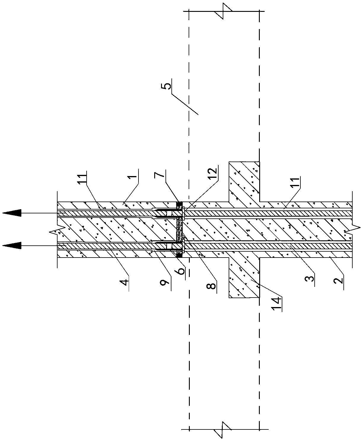
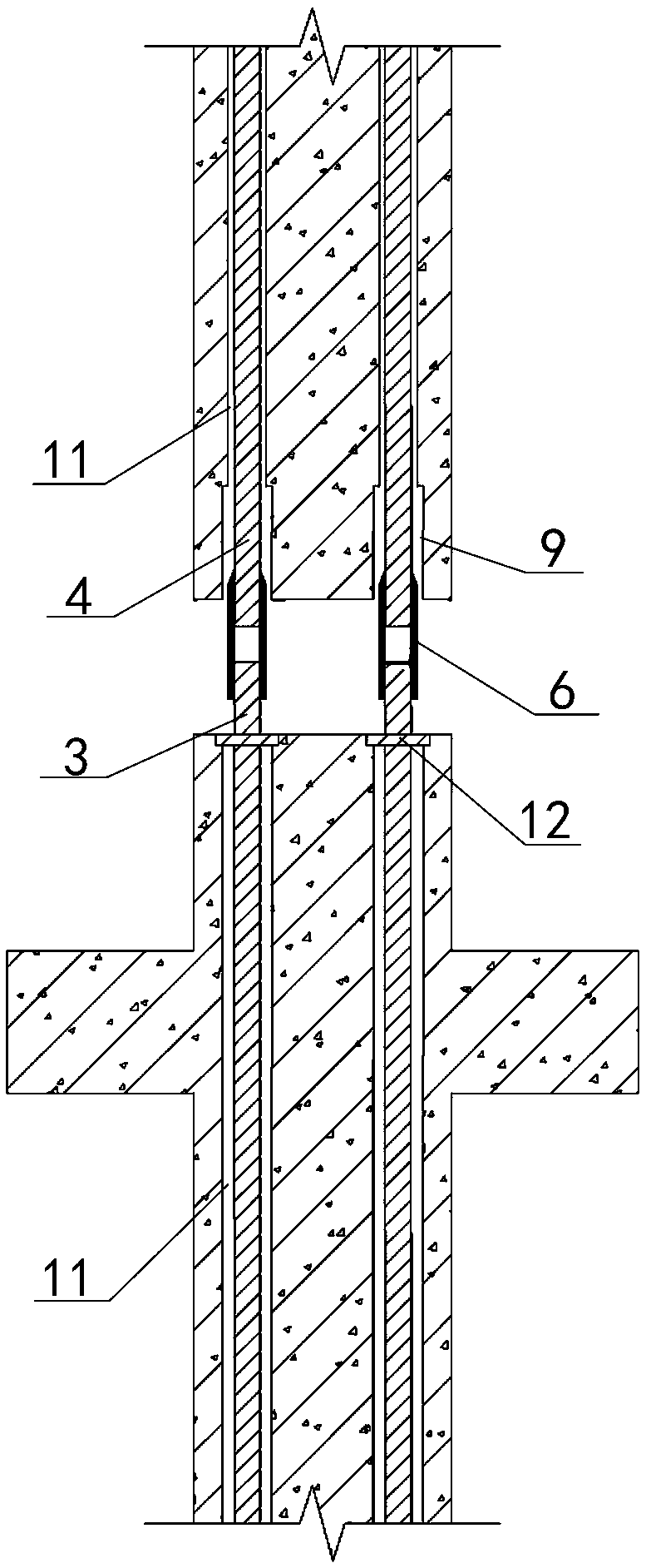
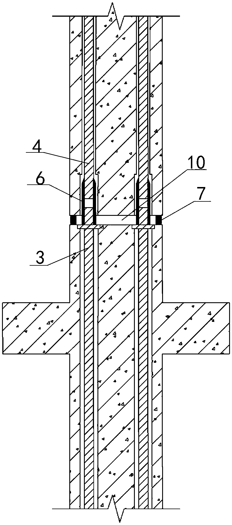
[0044] Examples see Figure 1-5 As shown, a pre-stressed reinforced concrete precast column vertical connection structure includes an upper reinforced concrete precast column 1 and a lower reinforced concrete precast column 2, where the lower reinforced concrete precast column 2 and the upper reinforced concrete precast column 1 connect nodes It is located above the connection node of the lower-level reinforced concrete precast column 2 and the frame beam 5.

[0045] The lower reinforced concrete precast column is provided with a set of long vertical prestressed holes, and each prestressed hole is penetrated with a lower column prestressed tendon 3, and the top of the lower reinforced concrete precast column 2 is embedded with prestress Anchor 12, the lower column pre-stressed tendons 3 extend upwards from the top surface of the lower-layer reinforced concrete precast column 2, the pre-stressed anchor 12 is sleeved on the lower-layer column pre-stressed tendons 3 and its top side...


PUM


Abstract

The invention discloses a prestressed reinforced concrete precast column vertical connecting structure and a construction method thereof. The prestressed reinforced concrete precast column vertical connecting structure comprises an upper-layer reinforced concrete prefabricated column, a lower-layer reinforced concrete prefabricated column, a steel bar connector, a leveling positioner and a sealinggrouting material, an anchoring space for accommodating the steel bar connector is formed in the bottom end of the upper-layer reinforced concrete prefabricated column; lower-layer column prestressedribs and upper-layer column prestressed ribs do not make contact in the steel bar connector, the leveling positioner is arranged on the top end face of the lower-layer reinforced concrete prefabricated column, the bottom end face of the upper-layer reinforced concrete prefabricated column abuts against the positioner, an initial tensioning gap is formed between the upper-layer reinforced concreteprefabricated column and the upper-layer reinforced concrete prefabricated column, and the initial tensioning gap is filled with the sealing grouting material. The pre-stress principle of pre-stresssteel bars is utilized, and standing and positioning of the columns are achieved through initial tensioning of the pre-stress steel bars in cooperation with the leveling positioner; and then through complete tensioning, reliable connection of the columns and the overall lateral performance and self-resetting performance of the structure are ensured.

Description

Technical field [0001] The invention belongs to the field of vertical connection of prefabricated columns, in particular to a connection structure of prestressed prefabricated columns and a construction method thereof. Background technique [0002] At present, the connection method of the stressed steel bars of the vertical prefabricated components generally adopts the steel sleeve grouting connection technology that is commonly used in the United States, Japan and other countries. However, due to the uneven construction skills of the workers, the connection quality of the grouting sleeve nodes is unreliable, the sleeve grouting is prone to improper grouting, the steel bars are connected in sections in the sleeve, and the prefabricated components are cracked in the later stage. Once an earthquake occurs The function is easy to break at the node and cause the component to fail. At the same time, the on-site construction of the grouting sleeve is large, the concrete pouring is dif...

Claims


Application Information

Patent Timeline
IPC IPC(8): E04B1/21E04C5/16E04B1/22E04B1/98E04H9/02
Inventor 雷远德邓烜叶烈伟李进波
Owner CHINA INST OF BUILDING STANDARD DESIGN & RES
Learn More