
Multi-dimensional buffer spherical suspension device

A suspension and multi-dimensional technology, applied in the direction of transportation and packaging, upper structure, upper structure of trucks, etc., can solve imperfect problems, increase contact area, ensure working comfort, and improve cushioning and vibration reduction performance effect

Active Publication Date: 2019-06-21
徐州博创建设发展集团有限公司
View PDF6 Cites 1 Cited by
  • Summary
  • Abstract
  • Description
  • Claims
  • Application Information

AI Technical Summary

Problems solved by technology

Passive noise reduction technology has made great achievements in vibration reduction and noise reduction, but the control of vehicle mid- and low-frequency noise and vibration is not perfect. For automobile vibration reduction technology, the main research focus is on power batteries or engine mounts As well as the cab suspension system, the cab, as the intuitive position of the human body, has always been the focus of research on shock absorption and noise reduction technology. With the advancement of technology, various cab suspension mechanisms continue to develop. Low vibration and noise, good comfort, but we all know that the road conditions are complex during the driving process of the car, and the change of the load spectrum is obtained: the vibration fluctuation in the vertical direction is dominant, and the vibration in other lateral directions also often exists, especially uphill and downhill Or on rough roads, roll vibration is the most important factor affecting the comfort of the cab, so it is very necessary to grasp the vibration reduction technology of the car cab from all dimensions

Method used


Image

  • Multi-dimensional buffer spherical suspension device
  • Multi-dimensional buffer spherical suspension device
  • Multi-dimensional buffer spherical suspension device

Examples


Embodiment Construction

[0025] The following will clearly and completely describe the technical solutions in the embodiments of the present invention with reference to the accompanying drawings in the embodiments of the present invention. Obviously, the described embodiments are only some, not all, embodiments of the present invention. Based on the embodiments of the present invention, all other embodiments obtained by persons of ordinary skill in the art without making creative efforts belong to the protection scope of the present invention.

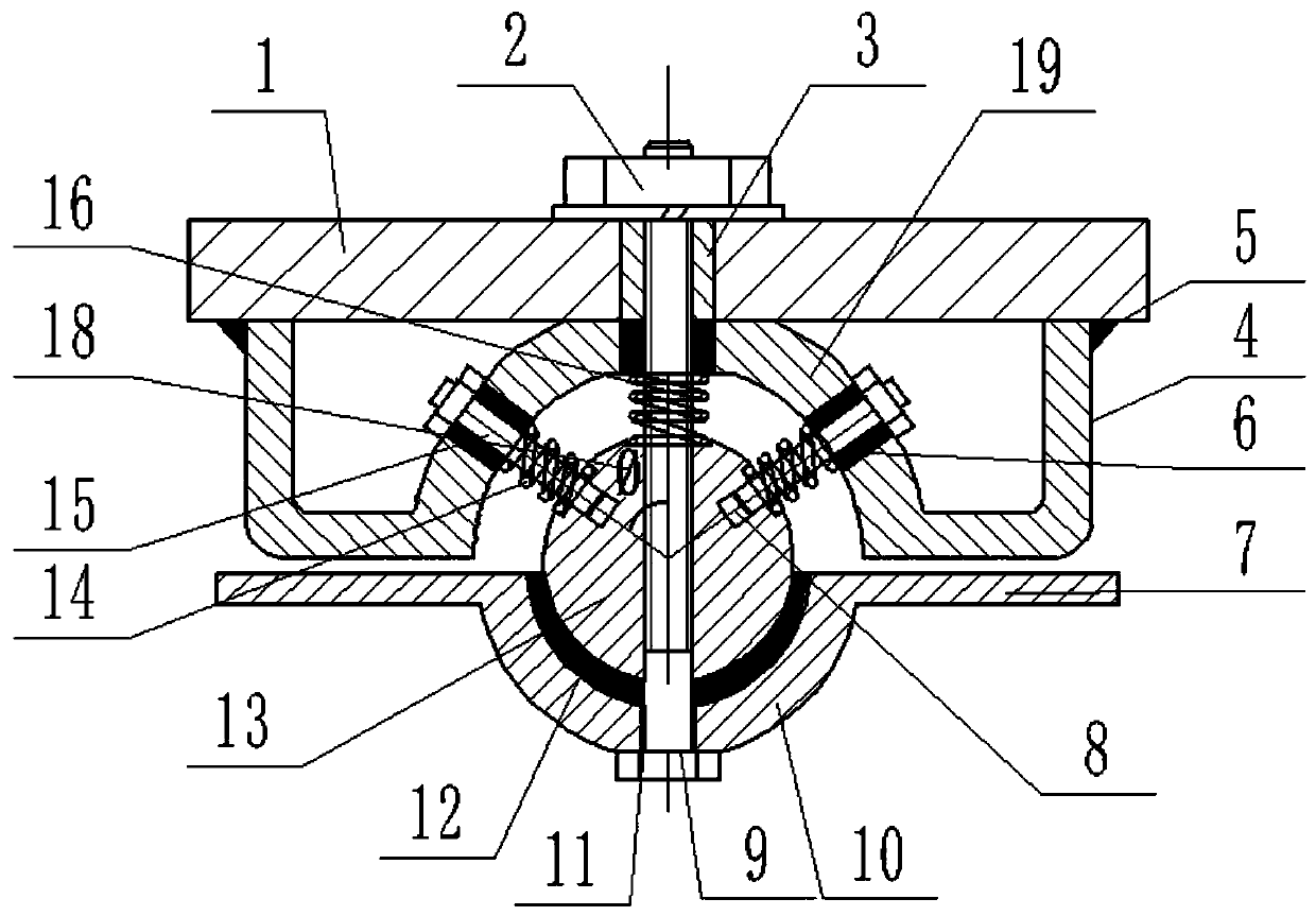
[0026] The purpose of the present invention is to provide a multi-dimensional cushioning spherical suspension device to solve the problems of the above-mentioned prior art, increase the contact area of ​​the cushioning and damping, improve the cushioning and damping performance of the entire suspension structure, and fully ensure The working comfort of series product vehicles.

[0027] Based on this, the multi-dimensional cushioning spherical suspension device...


PUM


Abstract

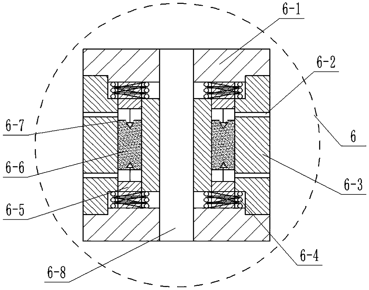
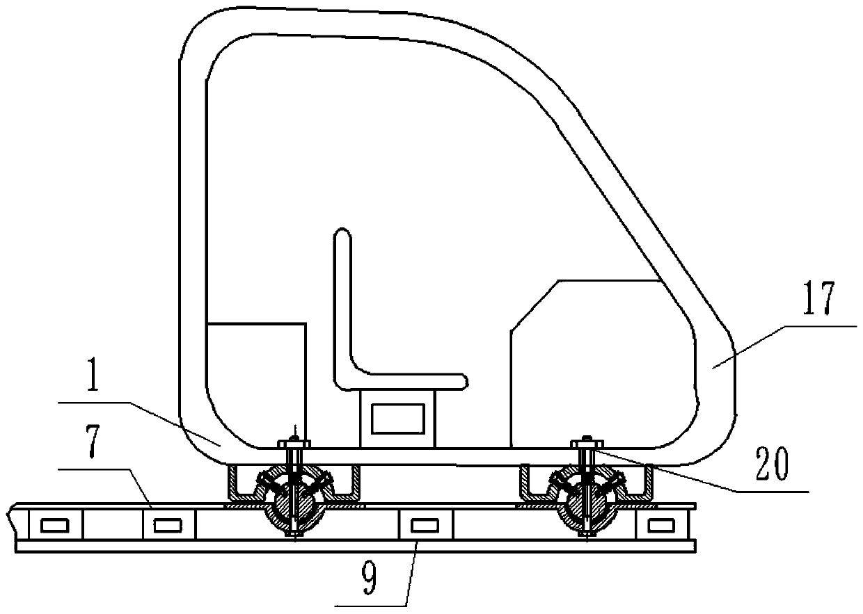
The invention discloses a multi-dimensional buffer spherical suspension device. The multi-dimensional buffer spherical suspension device comprises a cab bottom plate, a carframe plate, a suspension ball and a bracket plate, wherein the cab bottom plate is welded to the bottom position of a cab, four corner suspension points are all provided with perforations d3, the perforation d3 is an unthreadedhole, the bracket plate is welded and mounted on the bottom plate position of the cab at the bottom of the four corner suspension point, and vertical plates on both sides of the bracket plate are fixedly welded to the bottom plate position of the cab through fillet welds. According to the multi-dimensional buffer spherical suspension device, a main dimension spring cooperates with a suspension sleeve to bear the main direction vibration fluctuation, an auxiliary dimension spring cooperates with the suspension sleeve to bear the vibration fluctuation of the full-side azimuth dimension, and theentire buffer device can be pre-adjusted according to a load spectrum. The spherical contact between the suspension ball, a suspension pad and a fixed suspension groove increases the buffer damping contact area and improves the buffer damping performance of the entire suspension structure under various working environments.

Description

technical field [0001] The invention relates to the technical field of damping devices, in particular to a multi-dimensional buffer spherical suspension device. Background technique [0002] With the development of the automobile industry, people have higher and higher requirements for the comfort of automobiles, and thus higher and higher requirements for automobile vibration and noise reduction technology. Passive noise reduction technology has made great achievements in vibration reduction and noise reduction, but the control of vehicle mid- and low-frequency noise and vibration is not perfect. For automobile vibration reduction technology, the main research focus is on power batteries or engine mounts As well as the cab suspension system, the cab, as the intuitive position of the human body, has always been the focus of research on shock absorption and noise reduction technology. With the advancement of technology, various cab suspension mechanisms continue to develop. ...

Claims


Application Information

Patent Timeline
IPC IPC(8): B62D33/06
Inventor 王青亮项勇升
Owner 徐州博创建设发展集团有限公司
Learn More