
Intelligent lifting insulated arm pantograph

A pantograph, lifting technology, applied in the field of intelligent lifting insulating arm pantograph, can solve the problems of affecting service life, pantograph off-grid arcing, catenary and pantograph carbon slide wear increase, etc. Achieve the effect of prolonging the service life and improving the pantograph-network relationship

Inactive Publication Date: 2019-06-21
天津益昌电气设备股份有限公司
View PDF8 Cites 2 Cited by
  • Summary
  • Abstract
  • Description
  • Claims
  • Application Information

AI Technical Summary

Problems solved by technology

For example, the middle position of a catenary section is much lower than the nodes due to gravity, and the conduction height in the tunnel is further reduced due to construction difficulty and cost considerations. These circumstances force the pantograph to be lower than It works under the allowable working height range. At this time, the pantograph-catenary pressure is high, and the wear and tear of the catenary and the carbon slide of the pantograph increase, which seriously affects the service life of both; Elevate the catenary, forcing the pantograph to work higher than its allowable working height range. At this time, the pantograph-catenary pressure is small, which can easily cause the pantograph to break off the grid and arc. The arc also seriously affects the catenary and pantograph. Carbon Skateboard Lifespan
A small pantograph with a short bow arm should be used for low conductance heights, and a large pantograph with long bow arms should be used for high conductance heights. However, there is currently no pantograph in the world that can adapt to different conductance sections at the same time.

Method used


Image

  • Intelligent lifting insulated arm pantograph
  • Intelligent lifting insulated arm pantograph
  • Intelligent lifting insulated arm pantograph

Examples


Embodiment Construction

[0032] In order to enable those skilled in the art to better understand the technical solutions of the present invention, the present invention will be further described in detail below in conjunction with the accompanying drawings and preferred embodiments.

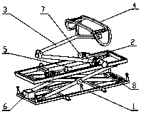
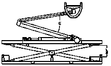
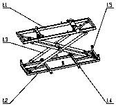
[0033] As shown in the figure, the present invention includes a lifting base 1, an insulating lower arm 2, an insulating upper arm 3, a bow head 4, a bow lifting cylinder 5, an intelligent control cabinet 6, an angle sensor 7, and a height sensor 8, wherein:

[0034] The mounting hole of the lower arm on the lifting base 1 is hinged to the mounting hole of the lower end of the insulating lower arm 2 through a connection assembly (shaft and fastener), and the mounting hole of the upper end of the insulating lower arm 2 is connected to the lower mounting hole of the insulating upper arm 3 through The components (shaft and fasteners) are hinged, the bow head 4 is hinged with the installation hole of the insulating upper arm ...


PUM


Abstract

The invention belongs to the technical field of mechanical devices and rail transit transmission, and particularly relates to an intelligent lifting insulated arm pantograph. The intelligent lifting insulated arm pantograph comprises a lifting base, a lower insulated arm, an upper insulated arm, a pantograph head with an insulated pantograph horn, a pantograph lifting cylinder, an intelligent control cabinet, an angle sensor and a height sensor. The intelligent lifting insulated arm pantograph adopts the design of the upper and lower arms and the insulated pantograph horn, so that an insulatorbetween the pantograph and a vehicle body is omitted, and equivalently the minimum working height of the pantograph is increased; when the lifting base is in a lifted state, equivalently the maximumworking height of the pantograph is decreased; the minimum working height and the maximum working height of the pantograph during working are optimized, and the pantograph is always kept at the more comfortable working height, so that the current collecting stability of the pantograph is guaranteed and the service life of a pantograph sliding plate is greatly prolonged.

Description

technical field [0001] The invention belongs to the technical field of mechanical devices and rail transit power transmission, and in particular relates to an intelligent lifting type insulating arm pantograph. Background technique [0002] The catenary is the main frame of the railway electrification project, and it is a special form of transmission line erected along the railway line to supply power to the electric locomotive. The catenary wire height (referred to as the guide height) refers to the vertical height of the contact line at the suspension positioning point from the rail surface. Under different situations and positions, the guide height varies greatly. For example, the middle position of a catenary section is much lower than the nodes due to gravity, and the conduction height in the tunnel is further reduced due to construction difficulty and cost considerations. These circumstances force the pantograph to be lower than It works under the allowable working he...

Claims


Application Information

Patent Timeline
Patent Type & Authority Applications(China)
IPC IPC(8): B60L5/32
Inventor 孙传新李相泉李维婉
Owner 天津益昌电气设备股份有限公司
Learn More