Fuel cell cooling system adopting organic working medium

A fuel cell and cooling system technology, which is applied in the direction of fuel cells, fuel cell additives, fuel cell heat exchange, etc., can solve the problems of unfavorable fast start-up and long time required for the system, achieve less system weight and increase net output The effect of power and rapid temperature rise

Pending Publication Date: 2019-06-18
武汉泰歌氢能汽车有限公司
View PDF2 Cites 2 Cited by
  • Summary
  • Abstract
  • Description
  • Claims
  • Application Information

AI Technical Summary

Problems solved by technology

At the same time, the rapid increase of cooling water is very unfavorable for the rapid start-up of the system. Due to the large specific heat capacity of water, a large amount of heat needs to be provided to heat the cooling water during the start-up phase, and the time required for cold start-up is longer

Method used


Image

  • Fuel cell cooling system adopting organic working medium

Examples


Embodiment 1

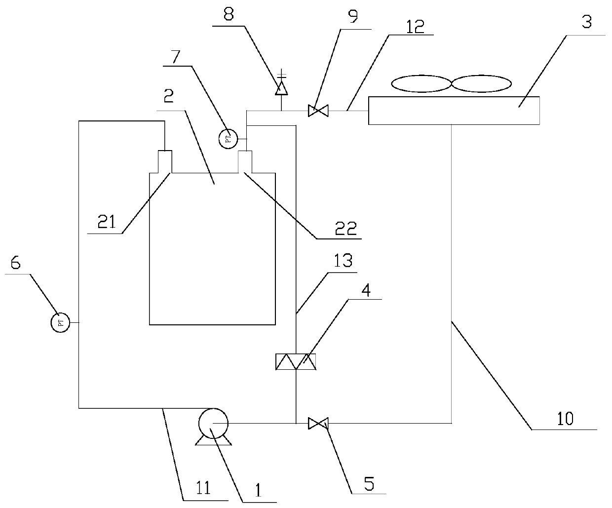
[0017] Please refer to figure 1 , Embodiment 1 of the present invention provides a fuel cell cooling system using an organic working medium, including a circulation pump 1, a fuel cell stack 2, a condenser 3, a PTC heater 4, and a data receiving device (not shown in the figure) and the control device, the circulation pump 1 is used to provide flow power and pressure for the fuel cell cooling system; the condenser 3 can use forced air cooling to condense the gaseous coolant flowing into it into a liquid coolant, and the condenser 3 can be each A kind of air-cooled or liquid-cooled heat exchange equipment; PTC heater 4 has constant temperature heating characteristics, the principle is that after the PTC heating plate is powered on, the self-heating temperature will increase the resistance value and enter the transition zone, and the surface temperature of the PTC heating plate will remain constant. , the temperature is only related to the Curie temperature of the PTC heating pla...

Embodiment 2

[0023] The only difference between the second embodiment of the present invention and the first embodiment is that an exhaust hole is provided on the fuel cell stack 2 at a position opposite to the water outlet 22 , the exhaust hole is communicated with the outlet of the condenser 3 , and the water outlet 22 Connected to one end of the PTC heater 4, the gaseous coolant flowing out of the fuel cell stack 2 flows into the condenser 3 through the exhaust hole to be condensed, and the liquid coolant flowing out of the fuel cell stack 2 flows out from the water outlet 22, Under the action of the circulating pump 1 , it returns to the fuel cell stack 2 .

[0024] The fuel cell cooling system provided by the present invention can automatically control the fuel cell stack 2 to react at a suitable temperature, so as to prolong the service life of the fuel cell stack 2; the present invention uses the phase change heat of the organic working medium to replace the traditional water display...


PUM


Abstract

The invention provides a fuel cell cooling system adopting an organic working medium. The fuel cell cooling system comprises a circulating pump, a fuel cell stack, a condenser, a PTC heater and a control device, wherein a water inlet and a water outlet are formed in the fuel cell stack; the coolant added in the fuel cell stack is a low-boiling-point organic working medium; the outlet of the condenser is communicated with the inlet of the circulating pump, and the outlet of the circulating pump is communicated with the water inlet of the fuel cell stack; the a water outlet of the fuel cell stack is communicated with the inlet of the condenser and one end of the PTC heater; the other end of the PTC heater is communicated with the outlet of the condenser; the control device controls opening or closing of the PTC heater and the circulating pump; when the temperature of the coolant in the fuel cell stack is lower than zero, the control device starts the PTC heater to heat the coolant; and when the temperature of the coolant in the fuel cell stack is higher than a rated temperature, the control device closes the PTC heater, and a gaseous coolant in the fuel cell stack flows into the condenser to be condensed.

Description

technical field [0001] The invention relates to the technical field of fuel cells, in particular to a fuel cell cooling system using organic working fluid. Background technique [0002] A fuel cell is a high-efficiency energy conversion device that does not produce any pollutants during use. It is expected to become an ideal source of electrical energy in the future. It essentially converts the chemical energy stored in the fuel (hydrogen) into electrical energy. The ideal The conversion efficiency is 83%. At present, the actual efficiency is generally 45-60%, while the efficiency of thermal power and nuclear power is about 30-40%. The reaction product of the fuel cell is water, and basically no harmful gas is emitted. [0003] Fuel cells need a suitable temperature to react, and the efficiency will be reduced if the temperature is too high or too low. Therefore, it is very important to carry out reasonable thermal management for fuel cells. On the one hand, a large amount...

Claims


Application Information

Patent Timeline
Patent Type & Authority Applications(China)
IPC IPC(8): H01M8/04007H01M8/04029H01M8/04223H01M8/04225H01M8/0432H01M8/0438
CPCY02E60/50
Inventor 马天才祖文强杜玮
Owner 武汉泰歌氢能汽车有限公司
Why Eureka
Try Eureka