Sparse automatic encoder optimized neural network-based power transmission line fault identification method
A sparse automatic encoder and transmission line technology, applied in the field of power transmission and distribution, can solve the problems of limited data samples, less label data, and cumbersome acquisition process, and achieve the effect of improving the accuracy of fault identification.
- Summary
- Abstract
- Description
- Claims
- Application Information
AI Technical Summary
Problems solved by technology
Method used
Image
Examples
Embodiment 1
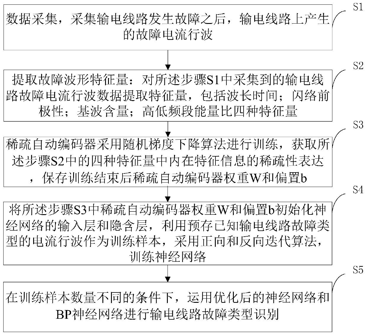
[0042] Such as figure 1 As shown, the embodiment of the present invention provides a transmission line fault identification method with a neural network optimized by a sparse autoencoder, including:
[0043] S1 data acquisition, collecting the fault current traveling wave generated on the transmission line after the transmission line fails;
[0044] S2 extracting fault waveform feature quantities: extracting feature quantities from the transmission line fault current traveling wave data collected in the step S1, including wavelength time; pre-flashover polarity; fundamental wave content; high and low frequency band energy ratio four feature quantities;
[0045] The S3 sparse autoencoder is trained using the stochastic gradient descent algorithm to obtain the sparse expression of the inherent feature information in the four kinds of feature quantities in the step S2, and save the sparse autoencoder weight W and bias b after the training ends;
[0046] S4 initializes the input ...
Embodiment 2
[0070] An embodiment of the present invention provides a method for identifying a fault type of a transmission line based on a neural network optimized by a sparse autoencoder, comprising the following steps:
[0071] 11. Data collection, collecting the fault current traveling wave generated on the wire after the transmission line fails, the fault current traveling wave data is the current traveling wave of 0.5ms before and after the fault occurs.
[0072] 12. Extracting fault waveform feature quantities: performing time domain and frequency domain analysis on the transmission line fault current traveling wave collected in step 11, the specific process is as follows:
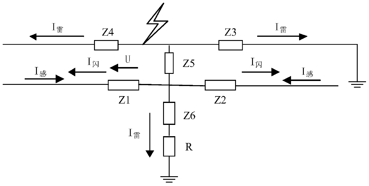
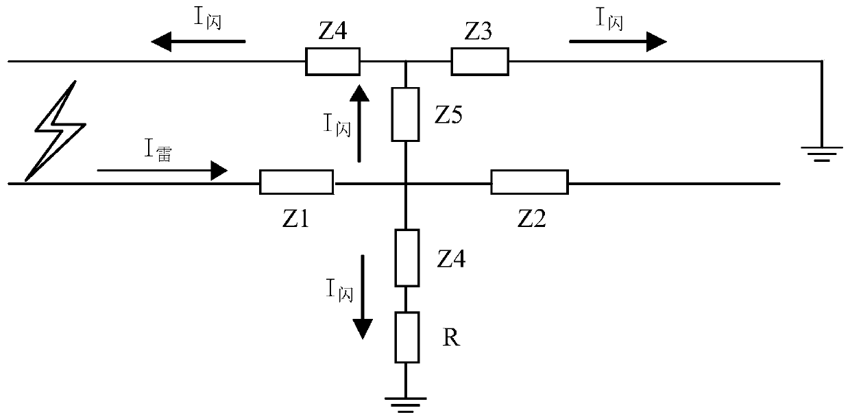
[0073] 121 analysis figure 2 , image 3 According to the current traveling wave path of counterattack and shielding faults in the transmission line, in the case of counterattack faults, before the insulator flashover, there is an induced current of reverse polarity on the transmission wire, but it does not exi...
PUM
 Abstract
Description
Claims
Application Information
 - R&D
- Intellectual Property
- Life Sciences
- Materials
- Tech Scout
- Unparalleled Data Quality
- Higher Quality Content
- 60% Fewer Hallucinations
Browse by: Latest US Patents, China's latest patents, Technical Efficacy Thesaurus, Application Domain, Technology Topic, Popular Technical Reports.
© 2025 PatSnap. All rights reserved.Legal|Privacy policy|Modern Slavery Act Transparency Statement|Sitemap|About US| Contact US: help@patsnap.com


