Spiral plate end surface welding device

A welding device and spiral plate technology, applied in auxiliary devices, welding equipment, auxiliary welding equipment, etc., can solve the problems of inability to meet the needs of spiral welding track welding, easy occurrence of internal injuries at splices, discontinuous welding process, etc. Welding quality, avoiding mechanical wear, the effect of fast welding speed

Inactive Publication Date: 2019-06-18
河北华环化工设备制造有限公司
View PDF5 Cites 4 Cited by
  • Summary
  • Abstract
  • Description
  • Claims
  • Application Information

AI Technical Summary

Problems solved by technology

However, in the welding channel process, manual welding is still the main method. The fundamental reason is that the welding track on the end face of the spiral plate heat exchanger is a spiral shape, and the distance between each point on it and the center of the spiral plate heat exchanger is different. Available automated welding equipment can only weld regular lines such as straight lines, arcs, and wavy lines, and cannot meet the welding needs of spiral welding trajectories
[0004] Hand welding is mostly used for manual welding. The quality of the welding process depends entirely on the welding skills and experience of the welding personnel. The welding quality is very unstable and rework problems often occur.
During rework, repair welding or re-welding after grinding is required, which greatly affects the production progress
Especially during handle welding, the welding process is discontinuous, and the joints of the welds are prone to internal damage, which requires key inspections, and the inspection cost is also very high

Method used


Image

  • Spiral plate end surface welding device
  • Spiral plate end surface welding device
  • Spiral plate end surface welding device

Examples


Embodiment 1

[0048] The present invention will be described in further detail below in conjunction with the accompanying drawings.

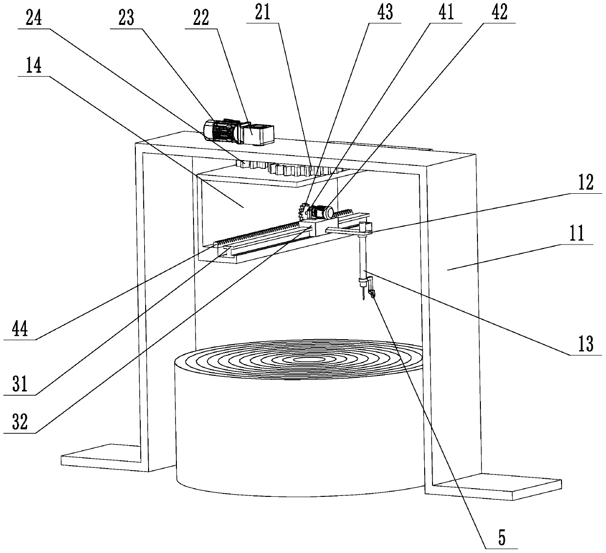
[0049] refer to figure 1 and Figure 5 ( Figure 5 The horizontal linear module section in the figure 1 The horizontal linear module part in the structure is the same), which is a spiral plate end face welding device disclosed by the present invention, the main body of which is the gantry 11, and the rest of the parts are directly or indirectly installed on the gantry.

[0050] The slewing support 21 is bolted on the gantry 11 , the turntable 14 is bolted on the slewing support 21 , and the turntable 14 is also bolted on the slewing support 21 . The rotary driving device is composed of a rotary reducer 22, a rotary servo motor 23 and a rotary gear 24, wherein the rotary reducer 22 is bolted to the gantry 11, the rotary servo motor 23 is installed on the income end of the rotary reducer 22, and the rotary gear 24 The key is connected to the output shaft of...

Embodiment 2

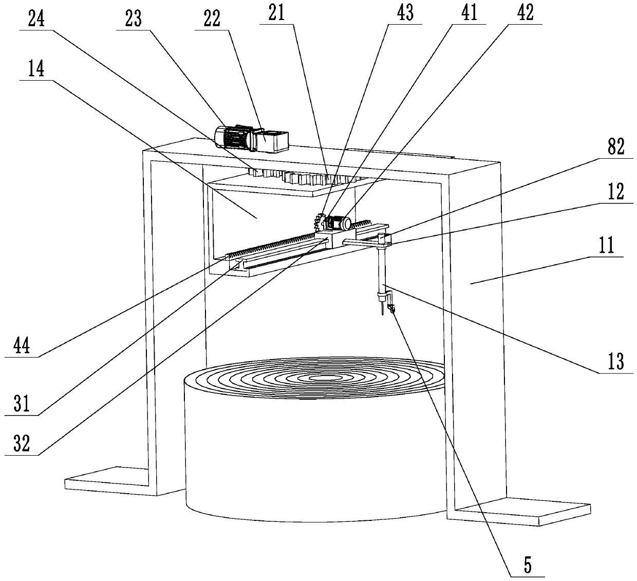
[0066] refer to figure 2 and image 3 In Embodiment 1, the welding torch 13 cannot move in the direction perpendicular to its trajectory, so the distance from the welding seam will be unstable, resulting in fluctuations in the welding height. Therefore, in this embodiment, a fine adjustment device is added between the welding torch 13 and the transverse slider 32 .

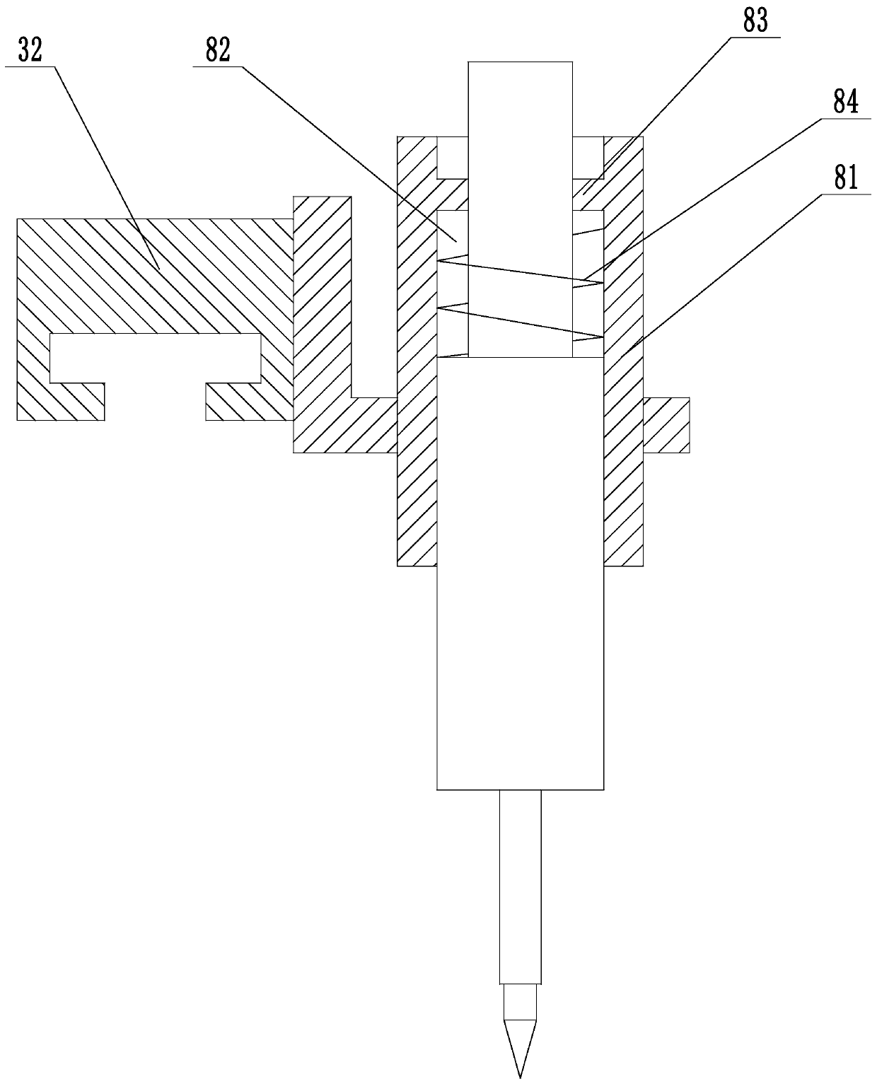
[0067] The main part of the fine-tuning device is a guide sleeve 81 fixed on the transverse slider 32, and a hole 82 is arranged on it, and an adjustment spring 84 is placed in the hole 82, and a boss 83 is provided on its inner wall, and the welding torch 13 moves from the bottom to the bottom. and inserted into the hole 82 . The two ends of the adjustment spring 84 respectively bear on the boss 83 and the welding torch 13, and the welding torch 13 slides in the hole 82 after being stressed, and the adjustment spring 84 is elongated or shortened thereupon.

[0068] The working principle of the fine-tuning dev...

Embodiment 3

[0071] refer to Figure 4 and Figure 5 , the welding torch 13 in embodiment 2 can only fluctuate within a small range. When the specification of the spiral plate heat exchanger to be welded changes, an additional corresponding lifting device needs to be added, which will bring additional operating steps. Therefore, this In the embodiment, a longitudinal distance adjustment part is added, and the longitudinal distance adjustment part can adjust the distance between the welding torch 13 and the spiral plate.

[0072] The longitudinal distance adjustment part is composed of a vertical operating table 61, a longitudinal linear module and a longitudinal driving device. Wherein the vertical operating platform 61 is fixed on the horizontal slide block 32 and can move linearly along the horizontal guide rail 31 under the drive of the horizontal slide block 32 .

[0073] The longitudinal linear module is composed of a longitudinal guide rail 62 and a longitudinal slider 63, wherein ...


PUM


Abstract

The invention relates to a spiral plate end surface welding device. The spiral plate end surface welding device comprises a portal frame, a rotating platform connected with the portal frame, a rotation driving device arranged on the portal frame and used for driving the rotating platform to rotate, a horizontal operating platform arranged on the rotating platform, a transverse linear module arranged on the horizontal operating platform, a welding gun arranged on the transverse linear module and a transverse driving device arranged on the transverse linear module and used for driving the transverse linear module to act, wherein a rotating bearing is arranged on the portal frame; the rotating platform is fixedly mounted on the rotating bearing; the rotation driving device comprises a rotating speed reducer arranged on the portal frame, a rotating servo motor connected with the rotating speed reducer and a rotating gear arranged on an output shaft of the rotating speed reducer. The spiralplate end surface welding device is used for welding spiral plates and has the characteristics of rapid welding speed, low welding cost and high operating efficiency.

Description

technical field [0001] The invention relates to the technical field of end face welding of spiral plate heat exchangers, in particular to a spiral plate end face welding device. Background technique [0002] The spiral plate heat exchanger is made of two parallel metal plates rolled into two spiral channels, and the heat exchange between the hot and cold fluids is carried out through the spiral plate wall. It has the advantages of small size, compact equipment, high heat transfer efficiency, The advantage of less metal consumption is suitable for dry liquid-liquid, gas-liquid, gas-gas convection heat transfer, steam condensation and liquid evaporation heat transfer, in chemical industry, petroleum, medicine, machinery, electric power, environmental protection, energy saving and heat conversion, etc. Industry has a wide range of applications. [0003] The processing flow of the spiral plate heat exchanger mainly includes blanking, splicing, rolling, welding channels, assembl...

Claims


Application Information

Patent Timeline
Patent Type & Authority Applications(China)
IPC IPC(8): B23K37/02
Inventor 赵国华赵子钰李建朋
Owner 河北华环化工设备制造有限公司
Why Eureka
Try Eureka