
Flying shear for rolled steel plates

A technology of flying shears and plates, which is applied in the direction of knives, shearing devices, and shearing equipment used in shearing devices. It can solve problems such as time-consuming cleaning, residues falling into gaps, troublesome replacement of flying shears, etc., to achieve extended Effect of service life and reduction of replacement frequency

Inactive Publication Date: 2019-06-18
ANHUI RISHENG MACHINERY MFG
View PDF7 Cites 2 Cited by
  • Summary
  • Abstract
  • Description
  • Claims
  • Application Information

AI Technical Summary

Problems solved by technology

[0003] When the flying shears used in existing steel rolling equipment are in use, the cutting blade is the key part of the flying shears, which is easy to be damaged, and it is troublesome to replace the body of the flying shears. In addition, there is a gap at the connection between the body and the roller, and the shearing process is difficult. There will be debris falling into the gap, and it will take time to clean up when replacing, so it will increase the replacement time of flying shears

Method used


Image

  • Flying shear for rolled steel plates
  • Flying shear for rolled steel plates
  • Flying shear for rolled steel plates

Examples


Embodiment

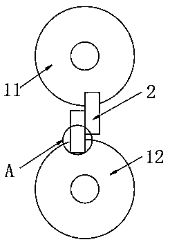
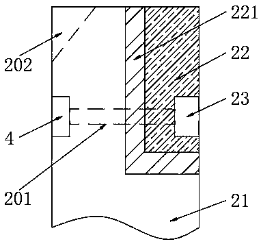
[0027] see Figure 1-5 , the present invention provides the following technical solutions: a flying shear for rolling steel plates, comprising a flying shear rotating roller 1 and a flying shear cutter body 2 installed on the outer wall of the flying shear rotating roller 1, and the flying shear rotating roller 1 includes a first rotating roller 11 and The second rotating roller 12, the first rotating roller 11 and the second rotating roller 12 are equipped with flying scissors body 2, and the two flying scissors bodies 2 are interlaced with each other. and the blade fixed clip 23, the flying scissors carrier 21 is provided with a clip through hole 201, and the blade fixing part 4 is installed in the clip through hole 201, and the flying scissors blade 22 is installed on the flying scissors carrier 21, And the flying scissors blade 22 is equipped with a blade fixing engaging part 23, the flying scissors carrier 21 and the flying scissors blade 22 are fixedly connected by the b...


PUM


Abstract

The invention belongs to the technical field of steel machining equipment, in particular to a flying shear for rolled steel plates. The flying shear comprises a flying shear rotating roller, and flying shear cutter bodies mounted on the outer wall of the flying shear rotating roller; the flying shear rotating roller comprises a first rotating roller and a second rotating roller; the flying shear cutter bodies are mounted on the first rotating roller and the second rotating roller; the two flying shear cutter bodies are staggered with each other; the flying shear cutter bodies comprise flying shear cutter carrying frames, flying shear cutter edges and edge fixed clamping pieces; the integral-molded flying shear cutter bodies consist of the flying shear cutter carrying frames, the flying shear cutter edges and the edge fixed clamping pieces; stress parts and bearing parts of the whole flying shear cutter bodies are separated; the flying shear cutter edges of the stress parts are fixed onthe flying shear cutter carrying frames through the edge fixed clamping pieces; and the stress shearing parts of the flying shear cutter bodies are arranged as high-hardness wear resisting steel withhigher stress, wear resistance and hardness, so that the service life of the flying shear cutter bodies can be prolonged, and the replacement frequency of the flying shear cutter bodies is reduced.

Description

technical field [0001] The invention belongs to the technical field of steel processing equipment, and in particular relates to a flying shear for rolling steel plates. Background technique [0002] Flying shears are a kind of shearing machines, which are used for transverse shearing of moving rolled pieces. Flying shears are mainly used for shearing medium and small billets, thin slabs, small section steel, and hot-rolled and cold-rolled strip steel. It is used to chop the edge of the plate cut by the disc shearing machine. According to the basic requirements and working characteristics of the flying shear, the flying shear generally consists of a shearing mechanism, a mechanism for adjusting the cutting length, a mechanism for adjusting the gap between cutting blades and transmission mechanism etc. [0003] When the flying shears used in existing steel rolling equipment are in use, the cutting blade is the key part of the flying shears, which is easy to be damaged, and it...

Claims


Application Information

Patent Timeline
IPC IPC(8): B23D25/02B23D35/00
Inventor 刘云飞甘文花
Owner ANHUI RISHENG MACHINERY MFG
Learn More