Friction power generator-based vibration-magnetic field energy hybrid collection device

A technology of friction generator and collection device, which is applied in the direction of friction generator, generator/motor, piezoelectric effect/electrostrictive or magnetostrictive motor, etc., and can solve the problem of collecting single vibration energy, single type of energy collection, Poor energy harvesting performance and other issues, to achieve the effect of improving energy harvesting efficiency and output voltage, increasing output power, and high power density

Inactive Publication Date: 2019-06-14
TSINGHUA UNIV
View PDF4 Cites 4 Cited by
  • Summary
  • Abstract
  • Description
  • Claims
  • Application Information

AI Technical Summary

Problems solved by technology

[0003] For a long time, in order to collect the ubiquitous vibration and magnetic field energy in the environment, a large number of devices for collecting these energies have emerged, but these devices inevitably have complex structures, low energy utilization, low power density, and single types of energy collection, etc. question
In 2008, A.Erturk and others in the United States proposed a cantilever vibration energy harvester based on the piezoelectric effect, but the problem is that the device can only output a considerable amount of energy when the cantilever is in an environment where the vibration frequency is equal to its resonant frequency. voltage, and the energy harvesting performance is poor in the vibration environment of other frequencies, and the collector can only collect a single vibration energy

Method used


Image

  • Friction power generator-based vibration-magnetic field energy hybrid collection device
  • Friction power generator-based vibration-magnetic field energy hybrid collection device
  • Friction power generator-based vibration-magnetic field energy hybrid collection device

Examples


Embodiment Construction

[0044] Embodiments of the present invention are described in detail below, examples of which are shown in the drawings, wherein the same or similar reference numerals designate the same or similar elements or elements having the same or similar functions throughout. The embodiments described below by referring to the figures are exemplary only for explaining the present invention and should not be construed as limiting the present invention.

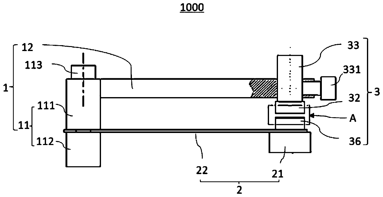
[0045] Refer below Figure 1 to Figure 6 A vibration-magnetic field energy hybrid collection device 1000 based on a friction generator according to an embodiment of the present invention will be described.

[0046] Such as Figure 1 to Figure 6 As shown, a vibration-magnetic field energy hybrid collection device 1000 based on a friction generator according to an embodiment of the present invention includes a support assembly 1 , a cantilever beam assembly 2 and a friction nano-power generation assembly 3 . The bracket assembly 1 includ...


PUM


Abstract

The invention discloses a friction power generator-based vibration-magnetic field energy hybrid collection device. The friction power generator-based vibration-magnetic field energy hybrid collectiondevice comprises a support assembly, a cantilever beam assembly and a friction nanometer power generation assembly, wherein the support assembly comprises a vertical post and a cross beam, one end ofthe cross beam is fixed with the vertical post, the cantilever beam assembly comprises a cantilever beam and a permanent magnet, the cantilever beam is arranged below the cross beam, one end of the cantilever beam is fixed on the vertical post, the permanent magnet is arranged on a lower surface of the other end of the cantilever beam, the friction nanometer power generation assembly comprises anupper electrode plate, a lower electrode plate and a polymer insulation sheet, the upper electrode plate is arranged below the other end of the cross beam, the lower electrode plate is arranged abovethe other end of the cantilever beam and is opposite to the upper electrode plate, the polymer insulation sheet is fixed on a upper surface of the lower electrode plate, and a gap is formed between the polymer insulation sheet and the upper electrode plate. The device can be used for simultaneously collecting vibration and magnetic field energy in an environment and has the characteristics of simple structure, high working applicability and high power density.

Description

technical field [0001] The invention relates to the technical field of friction power generation, in particular to a vibration-magnetic field energy hybrid collection device based on a friction generator. Background technique [0002] The rapidly developing wireless sensor network has broad application prospects in environmental monitoring, structural health monitoring, implanted medical detection, etc. The main bottleneck of these applications is self-sufficient energy. This demand has given birth to the generation and development of energy harvesting technology. In 2012, the research team of Wang Zhonglin, a professor at the Georgia Institute of Technology, invented the triboelectric nanogenerator, which can convert tiny mechanical energy into electrical energy by using the coupling of the triboelectric effect and the electrostatic induction effect. The various mechanical energy lost can be converted into electrical energy, which has broad application prospects. [0003] ...

Claims


Application Information

Patent Timeline
Patent Type & Authority Applications(China)
IPC IPC(8): H02N1/04H02N2/18
Inventor 丁状韩勤锴徐学平
Owner TSINGHUA UNIV
Why Eureka
Try Eureka