
Water faucet lubricating device for well drilling

A faucet and drilling technology, applied in the direction of engine lubrication, lubricating parts, engine components, etc., can solve the problems of complex structure, high labor intensity and high difficulty of the faucet, achieve significant economic and social benefits, reduce labor intensity, use long life effect

Inactive Publication Date: 2019-06-14
山东乐乐机械有限公司
View PDF0 Cites 2 Cited by
  • Summary
  • Abstract
  • Description
  • Claims
  • Application Information

AI Technical Summary

Problems solved by technology

Due to the poor working conditions of the faucet and negotiating lubrication conditions, it is often stuck during drilling, so that the relative rotating parts inside the faucet cannot rotate, causing the shell of the faucet to rotate with the rotating rod, and the connected high-pressure hose is not allowed to rotate. Therefore, very dangerous failures will occur, ranging from damage to equipment, production stoppage and delayed work, to twisting of the big rope in severe cases, causing the drilling tool to fall into the well, causing serious personal injury and equipment scrapping accidents
The reason for this problem is that the faucet is caused by poor lubrication.
The current faucet has no oil pressure gauge and no cleaning means during operation. The harmful substances produced in the use of this closed oil bath lubrication method cannot be removed in time, which will deteriorate the lubricating oil, cause bearing damage, and cause stuck faults.
[0003] In order to prevent the faucet from being stuck, at present, there is only enhanced maintenance. The lubricating oil of the faucet is required to be replaced every 800 hours. This maintenance method will waste a lot of diesel and lubricating oil. The structure of the faucet is complicated and the location is high. It is necessary to climb up to the faucet for oil change and cleaning. The workload is heavy, the difficulty is high, the labor intensity is high, and the drilling time is long.

Method used


Image

  • Water faucet lubricating device for well drilling
  • Water faucet lubricating device for well drilling

Examples


Embodiment Construction

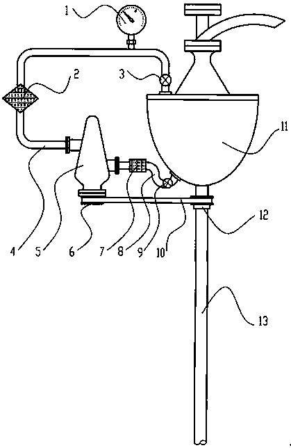
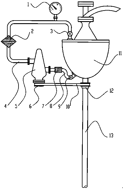
[0010] Attached below figure 1 Examples of the present invention will be described.

[0011] Depend on figure 1 It can be seen that the embodiment of the present invention includes a pressure gauge 1, an oil injection filter 2, an oil inlet valve 3, an oil injection pipe 4, an oil injection pump 5, a driven pulley 6, an oil return filter 7, an oil discharge pipe 8, and an oil discharge valve 9. Belt 10, faucet 11, driving pulley 12, rotating pipe 13, rotating pipe 13 passes through the middle of the water faucet 11, the rotating pipe 13 rotates during drilling, the faucet 11 does not rotate, and the upper end of the faucet 11 has an oil inlet. The oil port communicates with the inside of the faucet 11. There is an oil outlet at the bottom of the faucet 11. The lubricating oil added to the oil inlet can flow from the oil outlet. The inlet end of the oil injection pump 5 and one end of the oil discharge pipe 8 The other end of the oil discharge pipe 8 is connected to the oil o...


PUM


Abstract

The invention discloses a water faucet lubricating device for well drilling. An oil inlet is formed in the upper end of a water faucet, and an oil outlet is formed in the lower part of the water faucet; the inlet end of an oil injecting pump is connected with one end of an oil discharging pipe, and the other end of the oil discharging pipe is connected with the oil outlet in the lower part of thewater faucet; the discharging end of the oil injecting pump is connected with one end of an oil injecting pipe, and the other end of the oil injecting pipe is connected with the oil inlet in the upperpart of the water faucet; a driven belt wheel is installed on an input shaft of the oil injecting pump, and a driving belt wheel is installed on a rotating pipe; and the driving belt wheel rotates synchronously with the rotating pipe, and a belt is installed between the driven belt wheel and the driving belt wheel to enable the rotation of the driving belt wheel to be transmitted to the driven belt wheel. According to the water faucet lubricating device for the well drilling, power is provided for the oil injecting pump by utilizing the power of the rotating pipe, so that lubricating oil in the water faucet is circulated and filtered, and the lubricating oil is provided forcibly into the water faucet, so that the water faucet can maintain full and reliable lubrication; and the water faucet cannot be subjected to a stuck fault, workers do not need to climb to the water faucet to maintain the water faucet, and the labor intensity of the workers is greatly alleviated.

Description

technical field [0001] The invention is an auxiliary equipment for drilling in an oil field, in particular a faucet lubricating device for drilling. Background technique [0002] When drilling in the oil field, high-pressure fluids, such as mud and circulating water, must be injected into the downhole drill pipe. To inject high-pressure fluid into the downhole drill pipe, a faucet must be used. The shell is also connected with a high-pressure water hose, and the high-pressure water hose cannot rotate. Therefore, when the rotary pipe of drilling rotates, the shell of the water tap cannot rotate. That is to say, there are relatively rotating parts inside the faucet. In order to rotate freely and reduce the friction during rotation, several sets of bearings are installed inside the faucet. These sets of bearings need reliable lubrication to ensure the normal operation of the faucet. Due to the poor working conditions of the faucet and negotiating lubrication conditions, it is ...

Claims


Application Information

Patent Timeline
Patent Type & Authority Applications(China)
IPC IPC(8): F16N7/38F16N39/06
Inventor 刘景
Owner 山东乐乐机械有限公司
Learn More