Fabricated concrete cooling tower and construction method

A cooling tower and concrete technology, which is applied in building construction, construction, refrigeration plants, etc., can solve problems such as difficult construction and increased labor costs, and achieve the effects of reducing weight, reducing construction difficulty, and reducing the thickness of the upper layer

Pending Publication Date: 2019-06-14
刘全义
View PDF0 Cites 2 Cited by
  • Summary
  • Abstract
  • Description
  • Claims
  • Application Information

AI Technical Summary

Problems solved by technology

Working at heights is dangerous, and personnel with qualifications and rich experience in working at heights must be required. In this way, it is difficult to form a relatively high-end construction team in a short period of time, and the labor cost will increase accordingly.

Method used


Image

  • Fabricated concrete cooling tower and construction method
  • Fabricated concrete cooling tower and construction method
  • Fabricated concrete cooling tower and construction method

Examples


Embodiment 1

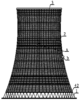
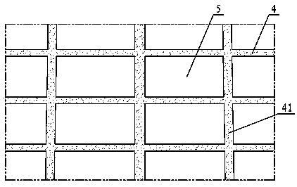
[0043] A concrete cooling tower shell, which consists of: a foundation 1, the upper part of the foundation is connected to the tower wall 2, the upper part of the tower wall is connected to the top hoop 3, the tower wall adopts an assembled structure, and the assembly The stressed member of the formula structure includes a horizontal concrete beam 4 and a hyperbolic concrete column 41 connected with the horizontal concrete beam, and the hyperbolic concrete column is a bottom-up cast-in-place concrete column in the shape of a hyperbolic generatrix A group of prefabricated slabs 5 are sequentially embedded in the stress-bearing members as the height of the cast-in-place concrete column rises, and finally form the cooling tower shell; The horizontal bottom beam 42 is poured, and the hyperbolic concrete column 41 is cast in-situ at the transverse connection position between the prefabricated slabs. The horizontal concrete beam 4 is cast in-situ at the connection position in the he...

Embodiment 2

[0045]In the concrete cooling tower shell described in Embodiment 1, the connection position of the prefabricated slab has an installation assistance mechanism, and the described installation assistance mechanism is equipped with a shear connecting plate 6 and / or a sinker on the edge of the prefabricated slab respectively. The head steel plate 61 is welded or threaded between the shear connecting plates of adjacent prefabricated panels; or the countersunk steel plates of the prefabricated panels on both sides are connected through the shear connecting plates;

[0046] Alternatively, countersunk steel plates or shear connecting pipes are respectively installed on the edge of the prefabricated slab, and the countersunk steel plate of the prefabricated slab on one side is connected to the shear connecting pipe of the prefabricated slab on the other side.

Embodiment 3

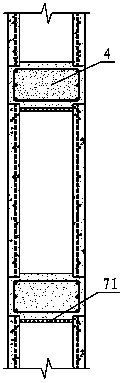
[0048] In the concrete cooling tower shell described in embodiment 1 or 2, there is a pouring channel 7 in the described prefabricated slab, and the horizontal distance between the described pouring channels in the vertical position is 200-800mm; the described pouring channel The upper part has a pouring cover plate 71, and the pouring cover plate is 30-80mm away from the edge of the arc-shaped prefabricated plate. The channel height is 25-75mm.


PUM

PropertyMeasurementUnit
Diameteraaaaaaaaaa
Thicknessaaaaaaaaaa

Abstract

The invention relates to a fabricated concrete cooling tower and a construction method. A traditional construction method is reverse formwork construction method or climbing formwork construction method and needs to complete at high altitude, and the degree of difficulty of high altitude construction is high, so that the construction period is relatively long. The fabricated concrete cooling towercomprises a foundation (1), wherein a tower wall (2) is connected to the upper part of the foundation, a top hoop (3) is connected to the upper part of the tower wall, and the tower wall adopts an fabricated structure; and stress components of the fabricated structure comprise horizontal concrete beams (4) and hyperbolic concrete columns (41) connected with the horizontal concrete beams, whereinthe hyperbolic concrete columns are cast-in-situ concrete columns from bottom to top in the shapes of hyperboloid bus bars, and a group of prefabricated plates (5) are sequentially embedded in the stress components along with the rise of the height of the cast-in-situ concrete columns to finally form a cooling tower shell; and a horizontal bottom beam (42) is cast in situ between the foundation and the prefabricated plates (5), the hyperbolic concrete columns (41) are cast in situ at the transverse connection positions between the prefabricated plates, and the horizontal concrete beams (4) arecast in situ at the height direction connection positions between the lower prefabricated plates and the upper prefabricated plates

Description

Technical field: [0001] The invention relates to a cooling tower, in particular to a hyperbolic cooling tower constructed by an assembled structure, and a construction method thereof. Background technique: [0002] The traditional construction method of the cooling tower is the inverted formwork construction method or the climbing formwork construction method. The main work of the above two construction methods needs to be completed at high altitude. Due to the relatively large diameter and height, the high-altitude construction is difficult, so the construction period is relatively short. long. Working at heights is dangerous, and personnel with qualifications and rich experience in working at heights must be required. In this way, it is difficult to form a relatively high-end construction team in a short period of time, and labor costs will increase accordingly. The prefabricated structure of the present invention aims to improve the long-standing backward situation of th...

Claims


Application Information

Patent Timeline
IPC IPC(8): E04H5/12E04G21/00
Inventor 刘全义刘旭
Owner 刘全义
Why Eureka
Try Eureka