
Longitudinal shear reinforcement and precast slab separated laminated slab composite beam

A technology of shear-resistant steel bars and prefabricated slabs, which is applied to floors, building components, buildings, etc., can solve the problems of inconvenient transportation of prefabricated slabs, inconvenient fixing and positioning of steel bars, and easy collision of beard bars, etc., to achieve reasonable force, simple structure, The effect of shortening the distance

Pending Publication Date: 2019-06-14
TSINGHUA UNIV
View PDF0 Cites 10 Cited by
  • Summary
  • Abstract
  • Description
  • Claims
  • Application Information

AI Technical Summary

Problems solved by technology

[0010] Aiming at the limitations and shortcomings of traditional concrete prefabricated slabs in the application of laminated slab composite beams, the present invention proposes a structural form of laminated slab composite beams in which longitudinal shear reinforcement and prefabricated slabs are separated, which can solve the inconvenience of traditional prefabricated slab transportation Easy to conflict, inconvenient fixing and positioning of additional steel bars, etc.

Method used


Image

  • Longitudinal shear reinforcement and precast slab separated laminated slab composite beam
  • Longitudinal shear reinforcement and precast slab separated laminated slab composite beam
  • Longitudinal shear reinforcement and precast slab separated laminated slab composite beam

Examples


Embodiment Construction

[0034] Below in conjunction with accompanying drawing, structure of the present invention, construction process are described further.

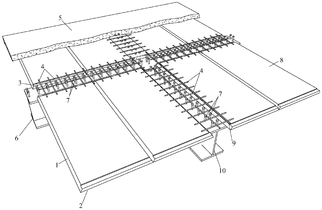
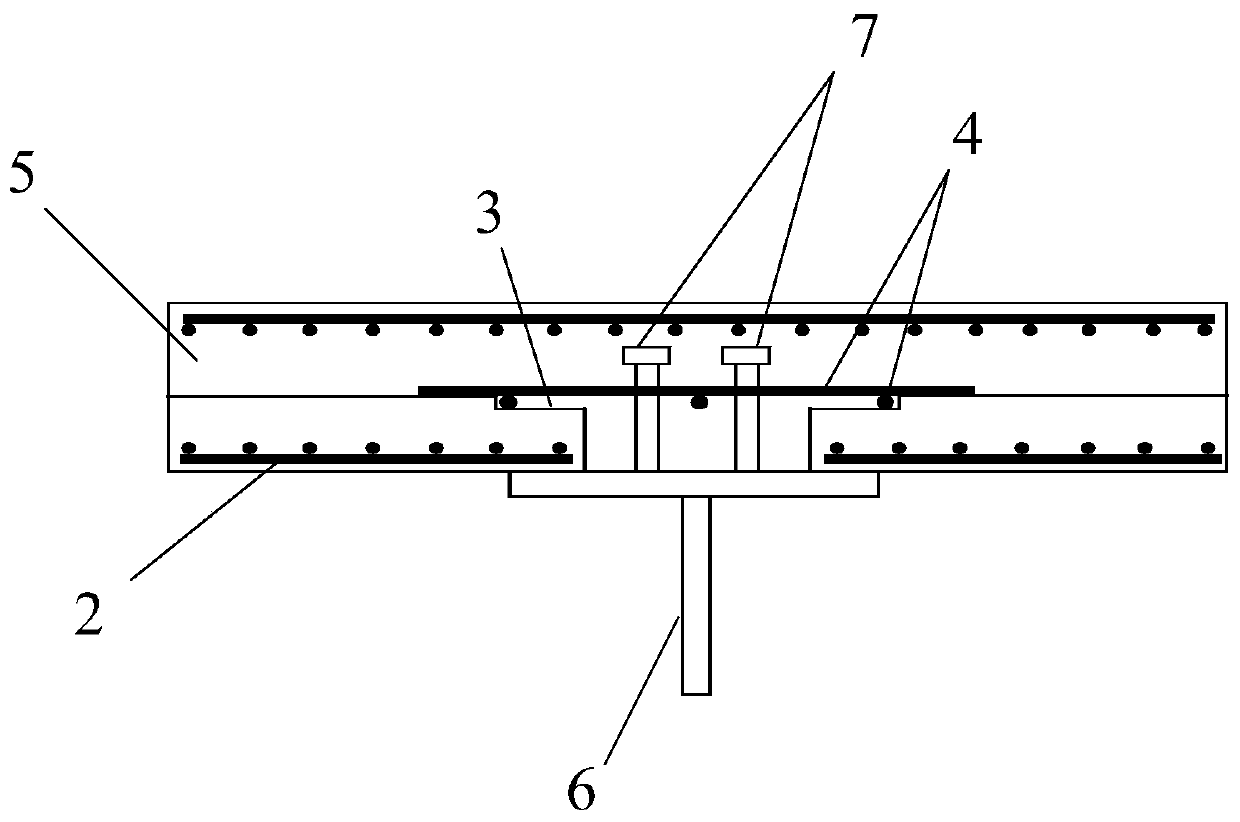
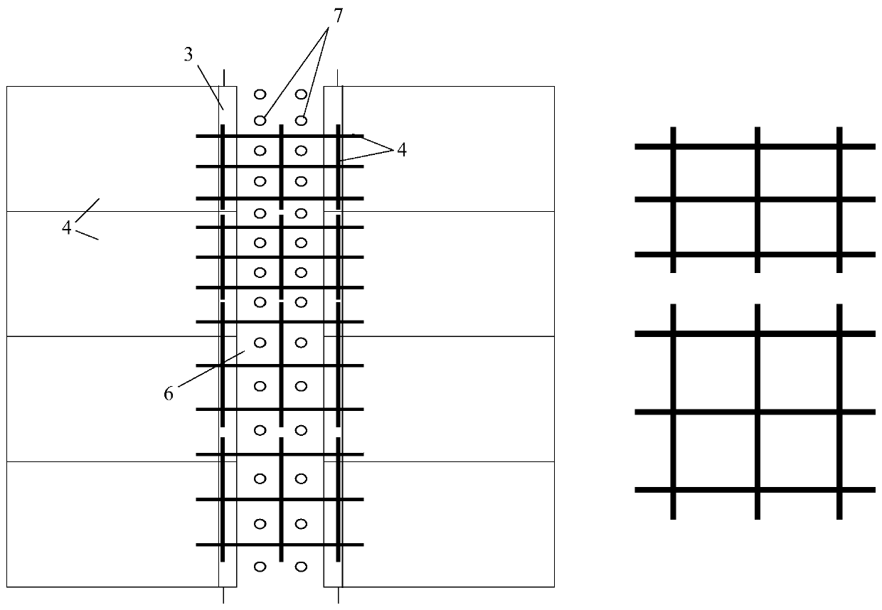
[0035] Such as figure 1As shown, the laminated slab composite beam separated from the longitudinal shear reinforcement and the prefabricated slab of the present invention comprises a concrete prefabricated slab (1) with an open end platform, an additional reinforcement mesh unit (4) in the platform and a post-cast concrete layer (5) , wherein the two ends of the prefabricated slab (1) cancel the beard bars, and the longitudinal steel bars (2) in the slab are flush with the plate ends of the prefabricated slab (1). When the factory is making prefabricated slab components, a stepped platform (3) is pre-opened at the end of the slab, and the end of the platform-opened concrete prefabricated slab (1) rests on the upper flange of the steel beam (6). When the prefabricated panel is installed, it will not conflict with the studs (7) on the upper fl...


PUM


Abstract

The invention relates to a longitudinal shear reinforcement and precast slab separated laminated slab composite beam, and belongs to the technical field of building structures. The longitudinal shearreinforcement and precast slab separated laminated slab composite beam comprises a concrete precast slab with a platform formed at the end, an additional reinforcement mesh unit and an upper concretepost-cast layer; no reinforcement stretches out of the slab end of the concrete precast slab with the platform formed at the end, meanwhile a step-shaped platform with the certain width is reserved atthe top of the precast slab, and the reinforcement mesh unit which is constituted by longitudinal and transverse reinforcements which are bundled is placed in the platform; and the transverse reinforcements play a longitudinal shear resistance role in the composite beam, the reinforcements in the beam length direction are parallelly placed in the step-shaped platform, and the positioning fixing effect is achieved. In the composite beam, traditional precast slab horizontal reinforcing bars are omitted, and through the modes that the step-shaped platform is formed at the slab end, and the reinforcement mesh unit is embedded, the longitudinal shear resistance problem of the composite beam and the longitudinal shear resistance reinforcement positioning problem are solved; and the longitudinalshear reinforcement and precast slab separated laminated slab composite beam is definite in force transmitting, convenient to construct, and suitable for laminated slab composite beam systems in thefields such as building engineering and bridge engineering.

Description

technical field [0001] The invention relates to a laminated slab composite beam separated from a prefabricated slab and longitudinal shear reinforcement, and belongs to the technical field of building structures. Background technique [0002] In structural systems such as prefabricated composite floors and composite beam bridges, composite beam systems have been widely used. In composite beams, longitudinal shear reinforcement is essential to prevent splitting damage. [0003] In the composite beam of the cast-in-place concrete flange, the transverse reinforcement of the concrete slab doubles as the longitudinal shear reinforcement of the composite beam. Because it is an on-site operation, the position of the horizontal reinforcement can be fine-tuned at any time according to the actual position of the stud when the reinforcement is bound. To avoid conflicts between studs and transverse reinforcement. [0004] In composite beams with composite slab concrete flanges, the tr...

Claims


Application Information

Patent Timeline
IPC IPC(8): E04B5/38E04B5/32
Inventor 陶慕轩李子昂聂鑫
Owner TSINGHUA UNIV
Learn More