
Design method of wing type of rotor wing of micro-miniature type rotor wing UAV (unmanned aerial vehicle) and product

A technology for unmanned rotor and aircraft, which is applied in the direction of aircraft, rotorcraft, instruments, etc., can solve the problems of low propeller aerodynamic efficiency, small size, low lift and drag of airfoil, etc., achieve good engineering practicability, improve aerodynamic efficiency, The effect of increasing the lift coefficient

Pending Publication Date: 2019-06-14
CENT SOUTH UNIV
View PDF0 Cites 13 Cited by
  • Summary
  • Abstract
  • Description
  • Claims
  • Application Information

AI Technical Summary

Problems solved by technology

[0005] There are still significant differences between the micro propeller airfoil and the traditional size propeller airfoil: (1) the size of this type of propeller is small, the diameter is often only a dozen inches or even a few inches, and the chord length is generally only a few centimeters; The propeller-like propeller has a much lower speed than the traditional aircraft propeller, and its flow Mach number is generally less than 0.3, which belongs to the range of incompressible flow. Therefore, the Reynolds number of its airfoil is extremely low, only about 100,000 or even lower
At present, there are few airfoils for this type of propeller, and the lift-drag ratio of the disclosed airfoils is low, so that the aerodynamic efficiency of the propeller is not high

Method used


Image

  • Design method of wing type of rotor wing of micro-miniature type rotor wing UAV (unmanned aerial vehicle) and product
  • Design method of wing type of rotor wing of micro-miniature type rotor wing UAV (unmanned aerial vehicle) and product
  • Design method of wing type of rotor wing of micro-miniature type rotor wing UAV (unmanned aerial vehicle) and product

Examples


Embodiment Construction

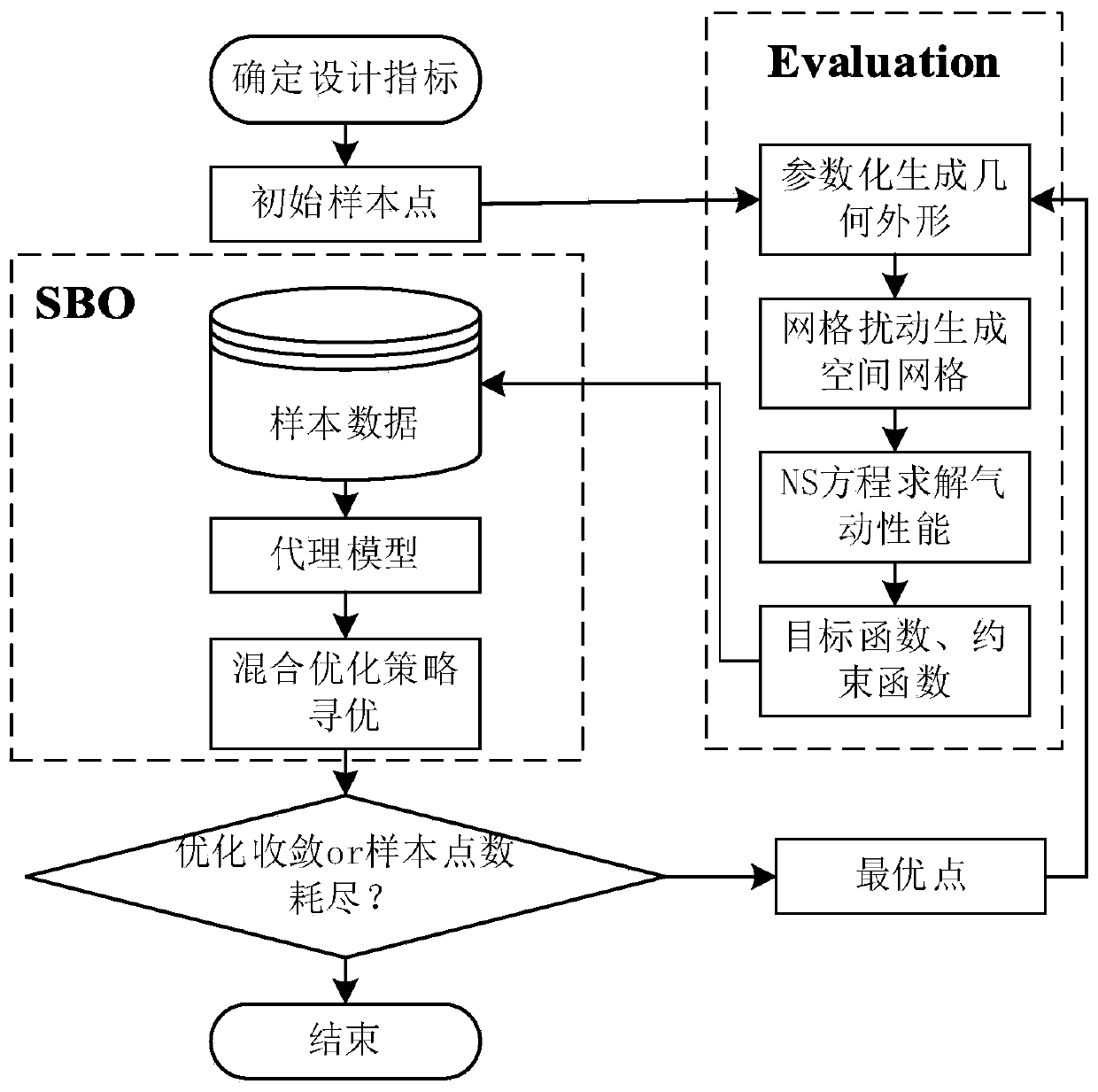
[0053] Taking the 15-inch propeller and the operating condition of 2930 revolutions per minute (r / min) as an example (rotor section chord length c = 2.5cm), how to use The above-mentioned design method is used to design the rotor airfoil with high lift-to-drag ratio. The process of the whole design method is as follows: figure 1 As shown, the specific design steps are as follows:

[0054] (1) According to the operating conditions of the three-dimensional rotor, calculate the design state of the airfoil, and select the reference airfoil

[0055] Since the diameter of the blade is 15 inches, that is, 38.1 centimeters, at the 70% radial section,

[0056] Rotation speed: V=2930 / 60×(2πR)×0.7=40.915m / s, where R is the radius of the rotor

[0057] Mach number: Ma=V / a=40.915 / 340.69=0.12, where a is the speed of sound

[0058] Reynolds number: Re=ρVc / μ=1.225×40.915×0.025 / (1.789×10 -5 )=7×10 4 , where ρ is the air density and μ is the air viscosity.

[0059] The angle of attack α...


PUM


Abstract

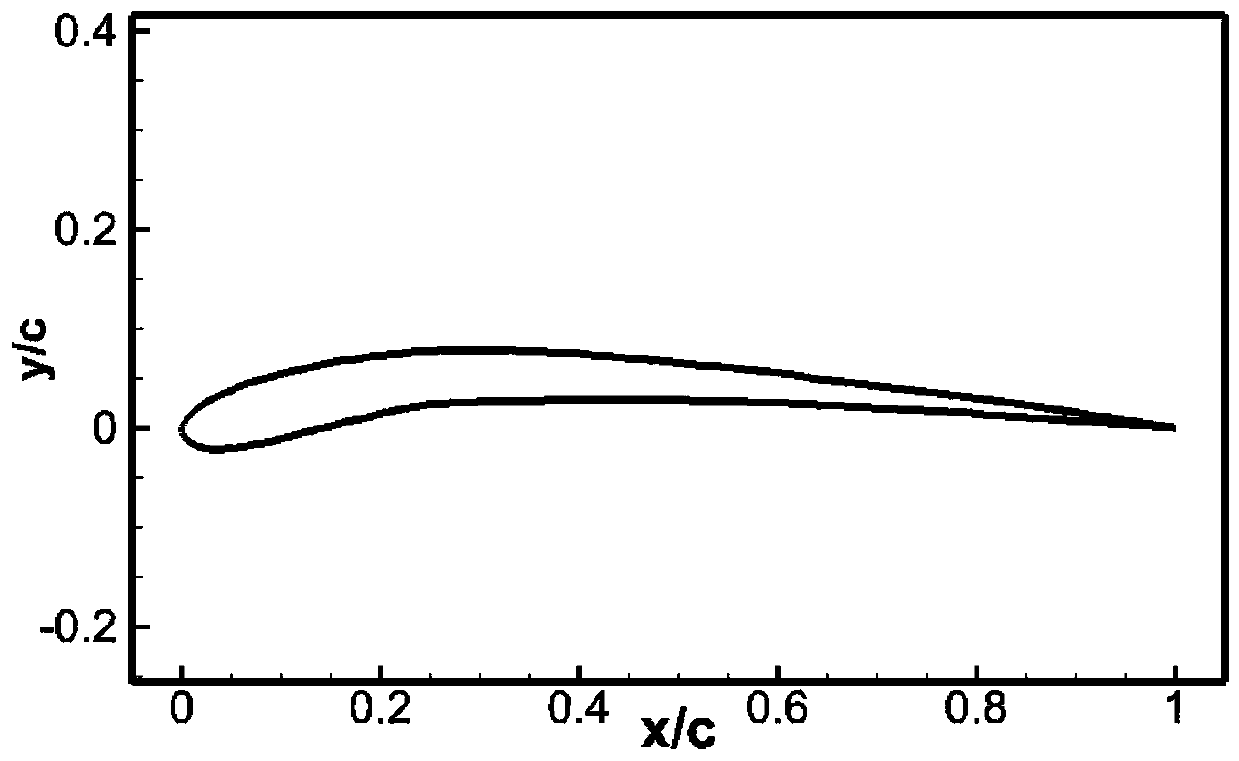
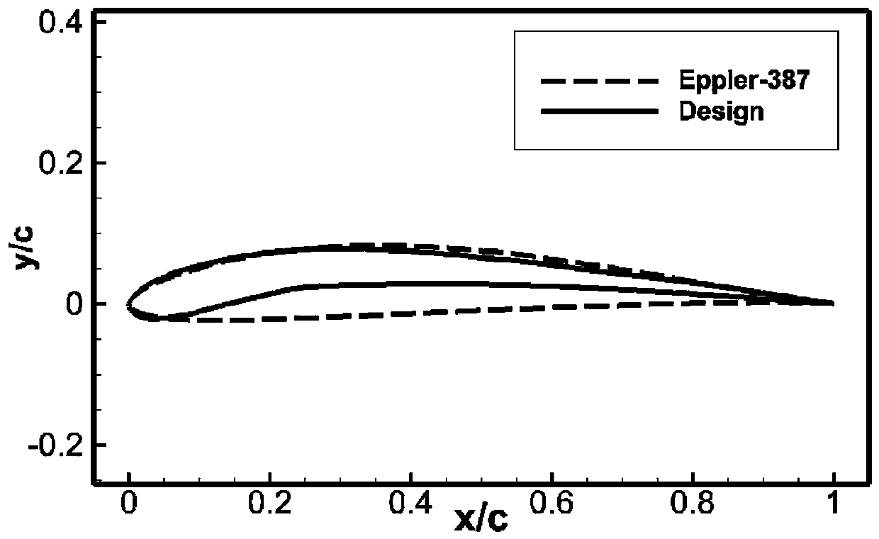
The invention discloses a design method of a wing type of a rotor wing of a micro-miniature type rotor wing UAV and a product, and the design method combines an efficient optimization algorithm basedon the agent model, a shape parameterization method based on the free deformation technique, a grid deformation method based on the radial basis function and an aerodynamic performance computing method based on the average Reynolds equation. Firstly, the design condition is determined, the incoming flow states, namely, the incoming flow Mach number, the Reynolds number and the angle of incidence,of the wing type are determined according to the main operation condition of a propeller and the radial position of the wing type on the blades; then the design index is determined; a lift-drag ratioas large as possible is obtained. According to the method, an Eppler 387 is taken as the datum wing type, the wing type whose whole curvature of the upper surface protrudes upward, front section of the curvature of the lower surface is concaved downward and rear section protrudes upward is designed, the relative thickness is small, the upper surface of the rear section is relatively flat, the whole curvature is large, the front section of the lower surface is concaved remarkably, the wing type has low total resistance coefficient and high lift coefficient, and accordingly the wing type has high lift-drag ratio and the aerodynamic efficiency is improved.

Description

technical field [0001] The invention relates to a micro-rotor unmanned aerial vehicle, in particular to a design method and product for a micro-rotor unmanned aerial vehicle rotor airfoil. Background technique [0002] As we all know, micro-rotor UAVs play an important role in many fields. This type of aircraft uses a motor to drive the propeller to rotate to generate a pulling force perpendicular to the plane of rotation. By adjusting the value of the pulling force of different propellers, the aircraft can hover, fly forward, and rise. The pulling force and torque of the propeller determine the aerodynamic efficiency of the propeller, and the aerodynamic efficiency of the propeller is a key factor for the cruising time of the aircraft. Similar to a fixed-wing wing, the basic element that constitutes the three-dimensional surface shape of the propeller is the blade element, that is, the tiny segment along the radial direction of the blade. Each blade element can be regarde...

Claims


Application Information

Patent Timeline
IPC IPC(8): B64C27/467G06F17/50
CPCY02T90/00
Inventor 刘俊罗世彬王逗
Owner CENT SOUTH UNIV
Learn More