Reduction gear with multistage speed reducing function

A reducer and spindle technology, which is applied to mechanical equipment, transmission parts, belts/chains/gears, etc., can solve the problems of complex structure of reducer, inconvenient maintenance or inspection, time-consuming and labor-intensive disassembly and assembly, and achieve the assembly process Smooth specification, high assembly efficiency, and easy assembly

Inactive Publication Date: 2019-06-11
CHANGAN UNIV
View PDF5 Cites 0 Cited by
  • Summary
  • Abstract
  • Description
  • Claims
  • Application Information

AI Technical Summary

Problems solved by technology

However, the existing RV reducer is easily affected by excessive impact load, and the bearing life is short. In addition, its weight is heavy and its overall size is large. At the same time, the structure of the reducer is complex, disassembly and assembly are time-consuming and labor-intensive, and maintenance or inspection is inconvenient.

Method used


Image

  • Reduction gear with multistage speed reducing function
  • Reduction gear with multistage speed reducing function

Examples


Embodiment Construction

[0017] The present invention is further described below in conjunction with accompanying drawing:

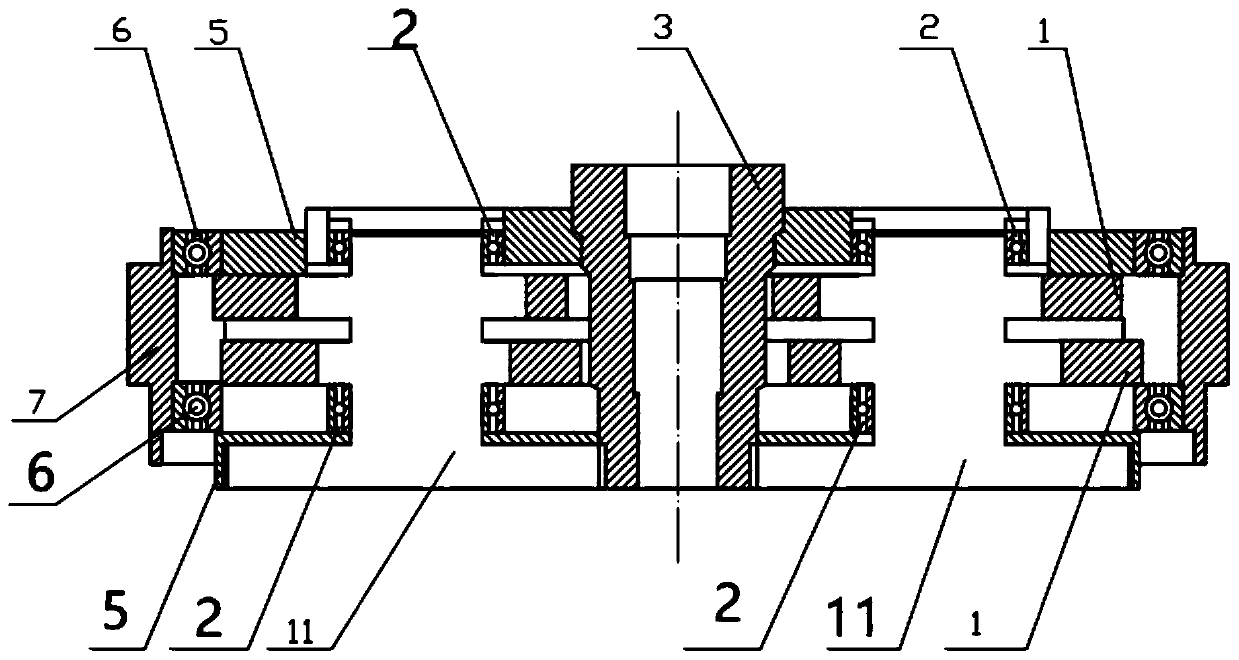
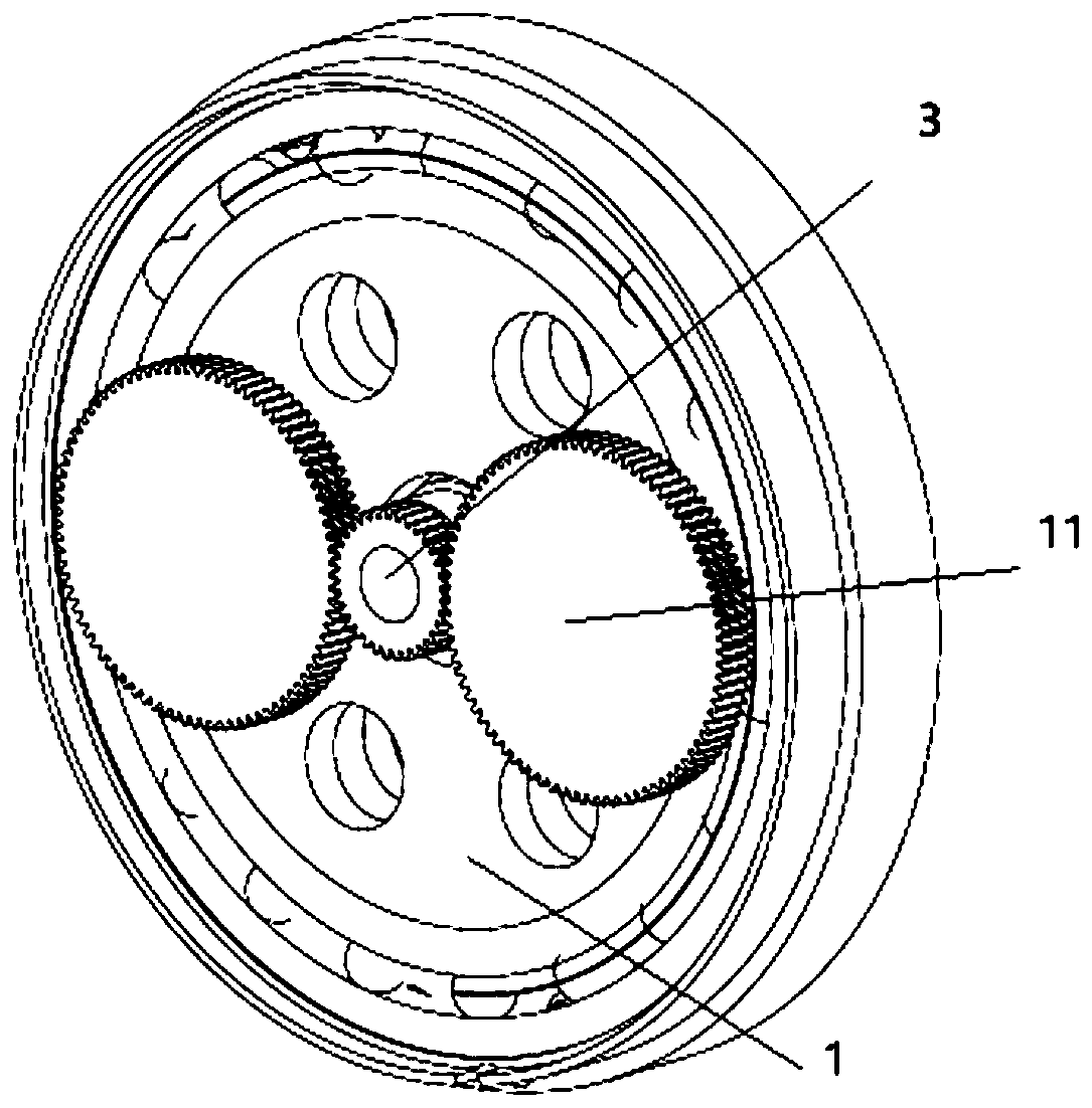
[0018] see figure 1 and figure 2 , a multi-stage deceleration reducer, including a main shaft 3, a planetary gear 11, a crankshaft 15, a housing 7 and a cycloidal pin wheel 1; the housing has a 7-bit hollow barrel structure, and the main shaft 3 is coaxially arranged on the housing 7 Geometric center; two crankshafts 15 are parallel to the main shaft 3 and arranged on a circle centered on the main shaft 3; the lower ends of the two crankshafts 15 are fixedly equipped with planetary gears 11, and the lower ends of the main shaft 3 are fixedly equipped with gears, and the gears are arranged on the two sides. The two planetary gears 11 are all meshed; the main shaft 3 is provided with two cycloidal pinwheels 1, and the cycloidal pinwheel 1 has a hole at the position of the crankshaft, and the crankshaft is set through the hole; the openings at both ends of the housing 7 are respe...


PUM


Abstract

A reduction gear with a multistage speed reducing function comprises a spindle, planet wheels, crankshafts, a shell and cycloidal-pin wheels. The shell is of a hollow barrel-shaped structure, and thespindle is coaxially arranged in the geometric center of the shell. The two crankshafts are parallel to the spindle, and are arranged on a circle with the spindle as the center at an equal radian. Theplanet wheels are fixedly arranged at the lower ends of the crankshafts, and a gear is fixedly arranged at the lower end of the spindle. The gear is engaged with the two planet wheels. The spindle issleeved with the two cycloidal-pin wheels, holes are formed in the positions, on the crankshafts, of the cycloidal-pin wheels, and the crankshafts penetrate through the holes. Outer ring ball bearings are arranged on openings in the two ends of the shell correspondingly, the outer rings of the outer ring ball bearings are fixedly connected with the inner side walls of the ends of the shell, and end covers are fixedly arranged on the inner rings of the two outer ring ball bearings. According to the reduction gear, output force is evenly distributed, the structure is simpler and more efficient,and the assembling process is simple and convenient.

Description

technical field [0001] The invention belongs to the technical field of speed reducers, in particular to a multi-stage speed reducer. Background technique [0002] Existing RV reducers are mainly used in industrial robots, machine tools, medical testing equipment, satellite receiving systems and other fields. However, the existing RV reducer is easily affected by excessive impact load, and the bearing life is short. In addition, it is heavy and has a large external dimension. At the same time, the structure of the reducer is complex, disassembly and assembly are time-consuming and labor-intensive, and maintenance or inspection is inconvenient. Contents of the invention [0003] The object of the present invention is to provide a multi-stage speed reducer to solve the above problems. [0004] To achieve the above object, the present invention adopts the following technical solutions: [0005] A multi-stage deceleration reducer, including a main shaft, a planetary wheel, a ...

Claims


Application Information

Patent Timeline
Patent Type & Authority Applications(China)
IPC IPC(8): F16H37/12F16H57/023
Inventor 封硕吕毅波田晓峰苏进展谢步庆谢廷船程博
Owner CHANGAN UNIV
Why Eureka
Try Eureka