
Connection structure of L-shaped superimposed shear wall edge member

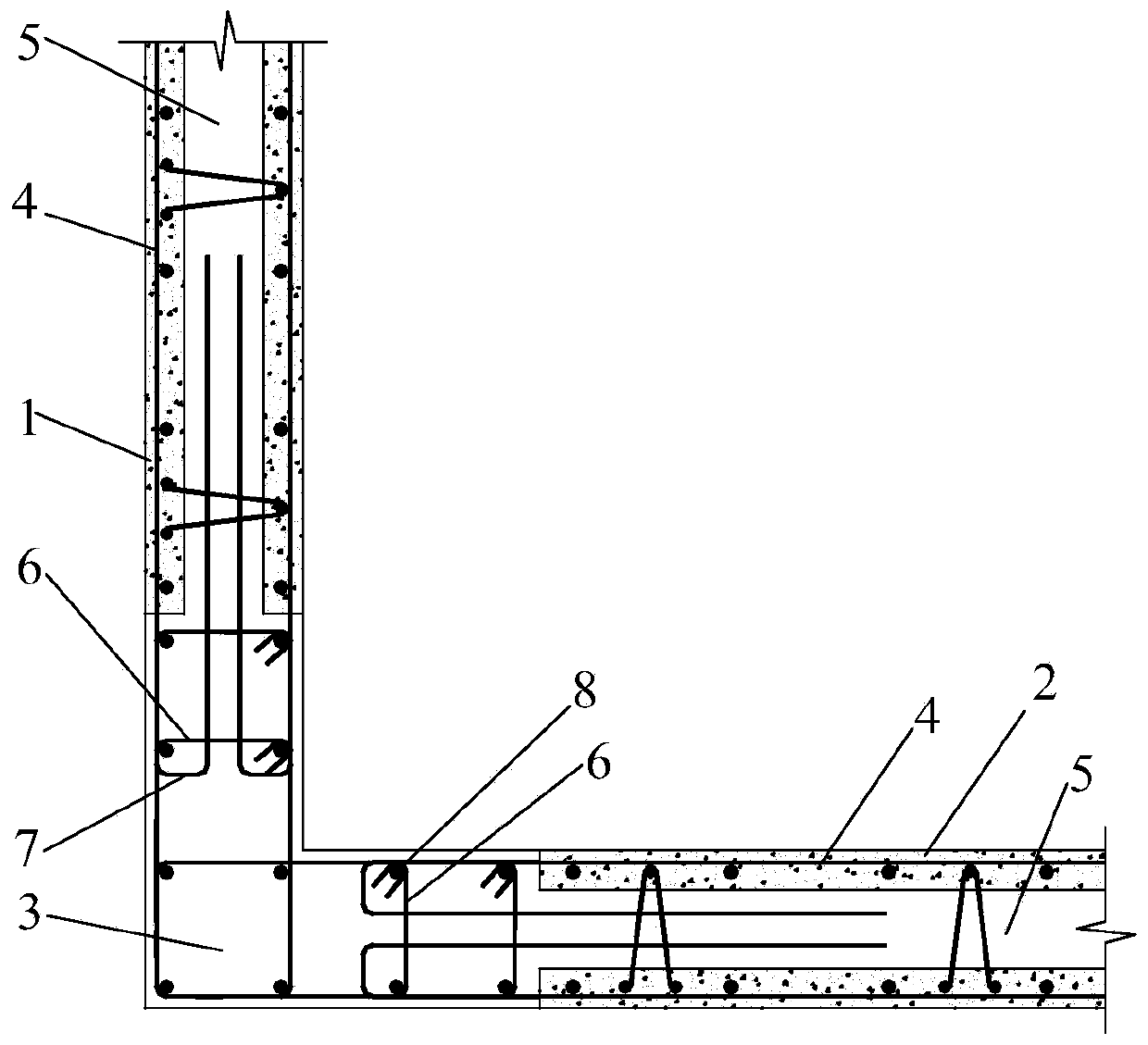
A technology of superimposed shear walls and edge components, applied to building components, building structures, walls, etc., can solve the problem of inability to effectively resist torsional deformation of L-shaped superimposed shear wall edge components, and inconvenient transportation of straight anchor horizontal steel bars With the problems of assembly and reduction of the effective area of ​​the cross-section at the seam, the effects of preventing local shear damage, reasonable force transmission, and improving the ability to coordinate deformation are achieved.

Active Publication Date: 2019-06-11
WUHAN UNIV OF TECH
View PDF2 Cites 0 Cited by
  • Summary
  • Abstract
  • Description
  • Claims
  • Application Information

AI Technical Summary

Problems solved by technology

At present, there are mainly two forms of traditional connection construction methods, that is, the cavity layer of the superimposed shear wall is additionally provided with a lap connection structure of reinforcement bars and the construction of a straight anchor connection structure with horizontal reinforcement in the superimposed shear wall. These two connection structures have respectively Certain deficiencies, such as the effective area reduction of the cross-section at the seams, the formation of weak layers, the insufficient utilization of horizontal steel bars in the edge components and prefabricated laminated layers, the exposed horizontal steel bars of straight anchors are too long to be convenient for transportation and assembly, etc.; at the same time, lap joints The U-shaped horizontal lapped reinforcement in the connection structure is built in the cavity layer, which cannot effectively resist the torsional deformation of the edge members of the L-shaped laminated shear wall, and the performance of the lapped joint under torsion is still unclear

Method used


Image

  • Connection structure of L-shaped superimposed shear wall edge member
  • Connection structure of L-shaped superimposed shear wall edge member

Examples


Embodiment Construction

[0016] The following will clearly and completely describe the technical solutions in the embodiments of the present invention with reference to the accompanying drawings in the embodiments of the present invention. Obviously, the described embodiments are only some, not all, embodiments of the present invention. Based on the embodiments of the present invention, all other embodiments obtained by persons of ordinary skill in the art without creative efforts fall within the protection scope of the present invention.

[0017] It should be noted that, in the case of no conflict, the embodiments of the present invention and the features in the embodiments can be combined with each other.

[0018] The present invention will be further described below in conjunction with the accompanying drawings and specific embodiments, but not as a limitation of the present invention.

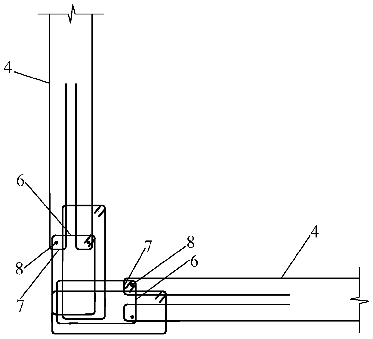
[0019] Such as figure 1 , figure 2 As shown, the connection structure of the L-shaped laminated shear wall ed...


PUM


Abstract

The invention relates to a connection structure of an L-shaped superimposed shear wall edge member. The connection structure comprises a superimposed flange wall board, a superimposed web board and anL-shaped corner edge member post-pouring area; horizontal steel bars in an inner blade superimposed layer and an outer blade superimposed layer in the superimposed flange wall board and the superimposed web board extend into the edge member post-pouring area by a certain length, then are bent and rotatably extend into cavity layers of the superimposed wall boards to form semi-open annular horizontal steel bars; horizontal hoops in the edge member post-pouring area are overlapped on the semi-open annular horizontal steel bars and bound to form a plurality of closed hoops; and vertical stress steel bars are inserted into the closed hoops, and concrete is poured into the cavity layers of the superimposed wall boards and the edge member post-pouring area to anchor the semi-open annular horizontal steel bars. According to the connection structure, by inserting the vertical stress steel bars into the closed hoops, the superimposed flange wall board, the superimposed web board and the L-shaped corner edge member post-pouring area are reliably connected, and the coordination deformation capability of the L-shaped corner edge member post-pouring area and the superimposed wall boards on thetwo sides is improved.

Description

technical field [0001] The invention relates to the technical field of construction, in particular to a connection structure of L-shaped superimposed shear wall edge components. Background technique [0002] L-shaped laminated shear walls with edge components are widely used in prefabricated high-rise building structures, especially when they are used as corner walls around the building, they are subjected to the largest force under the action of earthquake load and wind load, and are the most severely damaged parts. . [0003] Fully cast-in-place edge members of L-shaped laminated shear walls are the main type of edge members at present. In this type of edge members, is the connection structure between the post-cast concrete and the in-line laminated shear walls in two directions safe? Reliability is the key to ensure the overall stress of the edge members of the L-shaped laminated shear wall. At present, there are mainly two forms of traditional connection construction m...

Claims


Application Information

Patent Timeline
IPC IPC(8): E04B2/56
Inventor 谷倩赵端锋黄蓉华邓庆柯杨
Owner WUHAN UNIV OF TECH
Learn More