Vehicle hanging system
A suspension system and vehicle technology, applied in the field of vehicles, can solve the problems of increased vehicle cost, rocker arm deformation, unfavorable vehicle lightweight design, etc., to achieve the effect of increasing the force limit and increasing the rocker arm stroke
- Summary
- Abstract
- Description
- Claims
- Application Information
AI Technical Summary
Problems solved by technology
Method used
Image
Examples
Embodiment 1
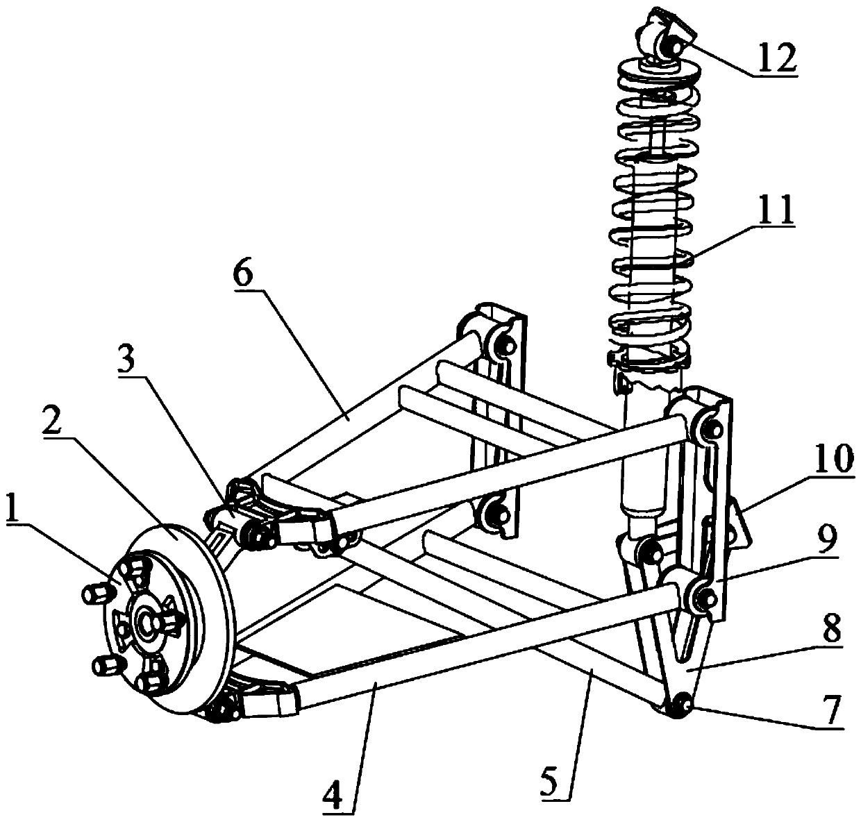
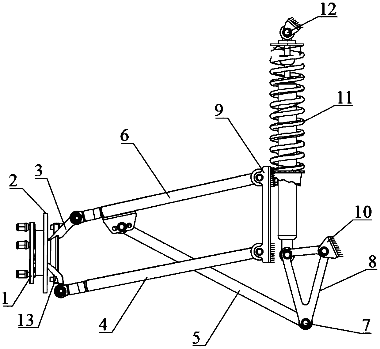
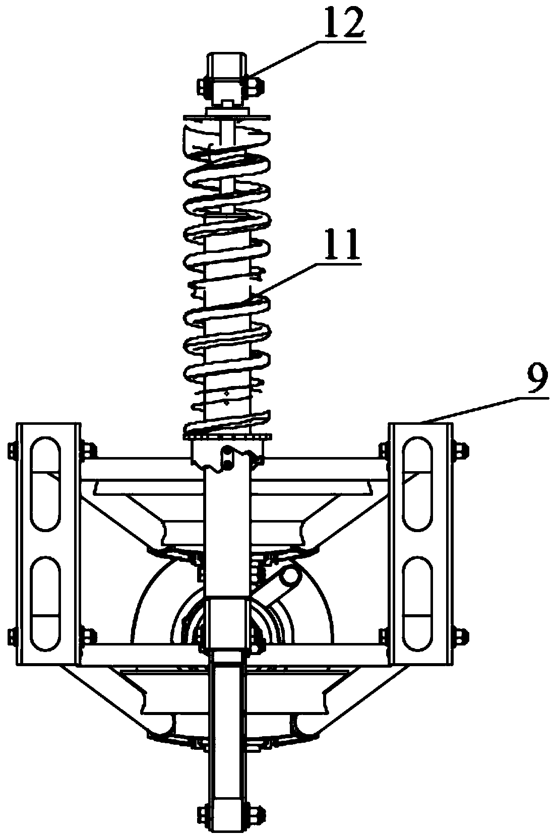
[0047] Please refer to Figure 1 to Figure 5 , Embodiment 1 of the present invention is:
[0048] A vehicle suspension system, including a shock absorber 11, a rocker arm, a bracket 8, a tie rod 5, a wheel hub 1, a brake disc 2, a rear horn, bolt fasteners 7, a rocker arm fixing lug 9, and a bracket fixing lug 10 As well as the shock-absorbing fixing lug 12 , the bracket 8 includes a bracket fixing point 81 , a shock-absorbing installation point 82 and a tie rod installation point 83 .
[0049] Such as figure 1It can be seen that the wheel hub 1 is arranged on the brake disc 2, one end of the rear horn is connected with the brake disc 2 on the side away from the back side of the wheel hub 1, and one end of the rear horn is connected with the rocker arm. The shock absorber 11 is located at the inner side of the rocker arm away from the brake disc 2 , one end of the shock absorber 11 is rotationally connected with the shock absorber installation point 82 , and the other end of...
Embodiment 2
[0052] Please refer to Figure 1 to Figure 5 , the second embodiment of the present invention is:
[0053] A vehicle suspension system, on the basis of the first embodiment above, the rocker arm includes an upper rocker arm 6 and a lower rocker arm 4, the other end of the pull rod 5 is connected to the upper rocker arm 6, and the rear horn includes an upper rear horn 3 and a lower rear horn Claw 13, one end of the upper rear horn 3 is connected with the brake disc 2 on the upper side away from the back of the hub 1, the other end of the upper rear horn 3 is connected with the upper rocker arm 6, and one end of the lower rear horn 13 is connected with the brake disc 2 It is connected at the lower side away from the back side of the wheel hub 1, and the other end of the lower rear horn 13 is connected with the lower rocker arm 4.
Embodiment 3
[0054] Please refer to Figure 1 to Figure 5 , Embodiment three of the present invention is:
[0055] A vehicle suspension system, on the basis of the first embodiment above, an angle sensor is arranged on the rocker arm. At the same time, corresponding sensors can also be installed according to the actual situation.
[0056] To sum up, in the vehicle suspension system provided by the present invention, since the first distance from the shock absorbing installation point to the fixed point of the bracket is smaller than the second distance from the installation point of the tie rod to the fixed point of the bracket, the larger displacement of the tie rod part is converted into The small displacement of the shock absorber can effectively increase the stroke of the rocker arm without increasing the stroke of the shock absorber, so as to adapt to the driving conditions of the all-terrain vehicle; at the same time, it can prevent the jumping of the rocker arm from being caught du...
PUM
 Abstract
Description
Claims
Application Information
 - R&D
- Intellectual Property
- Life Sciences
- Materials
- Tech Scout
- Unparalleled Data Quality
- Higher Quality Content
- 60% Fewer Hallucinations
Browse by: Latest US Patents, China's latest patents, Technical Efficacy Thesaurus, Application Domain, Technology Topic, Popular Technical Reports.
© 2025 PatSnap. All rights reserved.Legal|Privacy policy|Modern Slavery Act Transparency Statement|Sitemap|About US| Contact US: help@patsnap.com


