Rotor magnetic-field sine permanent-magnet reluctance synchronous motor rotor structure
A reluctance synchronization and motor rotor technology, applied in the direction of magnetic circuit shape/style/structure, magnetic circuit rotating parts, etc., can solve the problem of large harmonic content of air gap magnetomotive force, large output torque ripple, and reluctance distribution Inhomogeneity and other problems, to achieve the effect of reducing eddy current loss, reducing harmonic content, and improving operating efficiency
Active Publication Date: 2019-06-07
SOUTHEAST UNIV
View PDF5 Cites 0 Cited by
- Summary
- Abstract
- Description
- Claims
- Application Information
AI Technical Summary
Problems solved by technology
However, the setting of the multi-layer magnetic barrier of the rotor makes the reluctance distribution uneven, the harmonic content of the air gap magnetomotive force is large, and the ripple torque is high
The addition of permanent magnets leads to the cogging torque, which together with the ripple torque leads to the disadvantage of large output torque ripple of the multi-layer magnetic barrier permanent magnet reluctance synchronous motor
Method used
View moreImage
Smart ImageViewing Examples
Examples
Embodiment 1
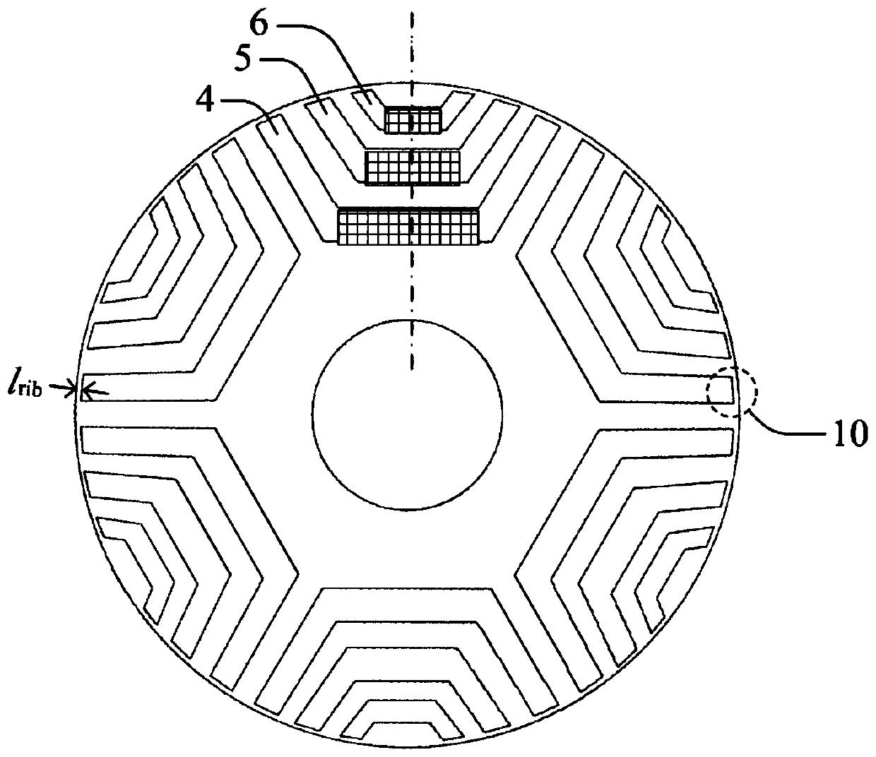
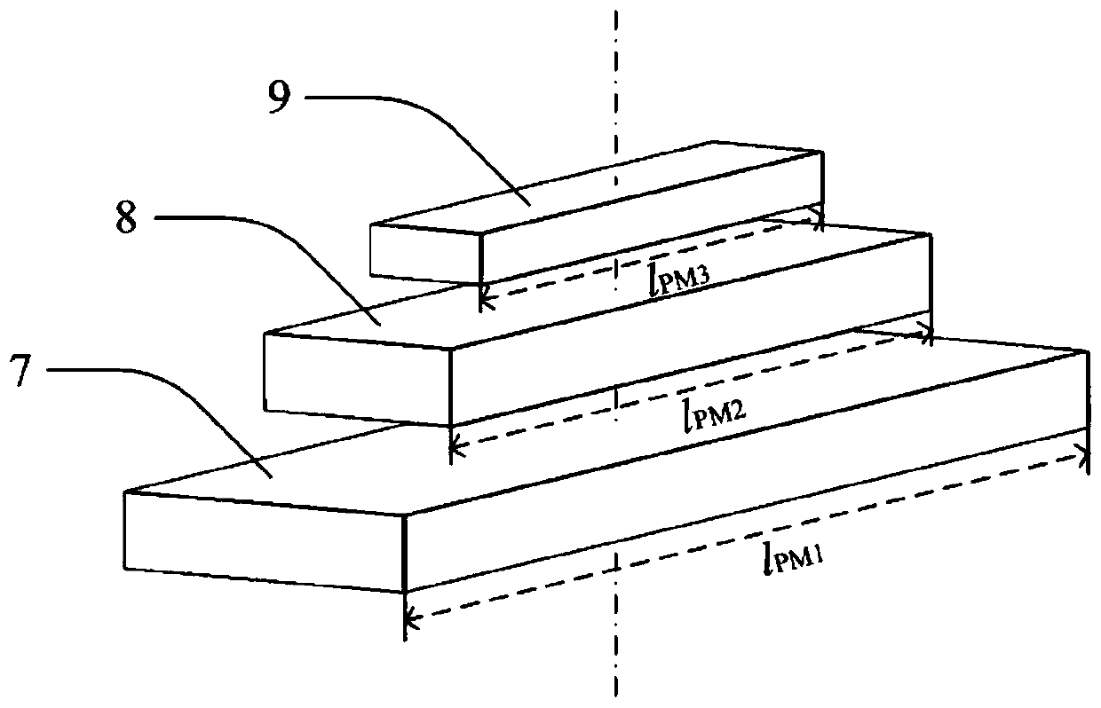
[0022] This embodiment is a 6-pole permanent magnet reluctance synchronous motor rotor, P=6. Other parameters are: l R =50mm, l rib = 0.5mm, l PM1 =50mm, l PM2 = 43.3 mm, l PM3 = 25mm.
Login to View More PUM
| Property | Measurement | Unit |
|---|---|---|
| Length | aaaaa | aaaaa |
Abstract
The invention discloses a rotor magnetic-field sine permanent-magnet reluctance synchronous motor rotor structure. The rotor magnetic-field sine permanent-magnet reluctance synchronous motor rotor structure comprises a central rotation shaft and a rotor core, wherein the rotor core sleeves the central rotation shaft, P through groove groups are uniformly formed in positions, encircling the centralrotation shaft, of the rotor core and are same in shape and size, P is rotor magnetic poles, each through groove group comprises a plurality of through grooves, permanent magnets are arranged in thethrough grooves, the polarities of the permanent magnets in the same through groove group are same, the polarities of permanent magnets in two adjacent through groove groups are different, and the lengths of the permanent magnets in the same through groove group are different. By arranging the lengths of the permanent magnets in the same through groove group to be different, the sine performance of a rotor magnetic field can be improved, and the ripple torque is reduced. By the rotor magnetic-field sine permanent-magnet reluctance synchronous motor rotor structure, the harmonic content of an air gap magnetic field can be reduced, the eddy-current loss is reduced, and the running efficiency of the motor is improved.
Description
technical field [0001] The invention relates to a permanent magnet reluctance synchronous motor rotor structure, in particular to a rotor magnetic field sinusoidal permanent magnet reluctance synchronous motor rotor structure. Background technique [0002] There are magnetic barriers distributed in the rotor of multi-layer magnetic barrier permanent magnet reluctance synchronous motor according to certain rules, which are used to increase the salient polarity of the motor to generate reluctance torque. Permanent magnets are embedded in the magnetic barrier to further improve the torque of the motor. density and power factor. However, the setting of multi-layer magnetic barriers in the rotor makes the reluctance distribution uneven, the harmonic content of the air gap magnetomotive force is large, and the ripple torque is high. The addition of permanent magnets leads to cogging torque, which together with the ripple torque leads to the disadvantage of large output torque rip...
Claims
Login to View More Application Information
Patent Timeline
 IPC IPC(8): H02K1/27
Inventor 林明耀孔永伍锡坤张旭
Owner SOUTHEAST UNIV
Features
- R&D
- Intellectual Property
- Life Sciences
- Materials
- Tech Scout
- Unparalleled Data Quality
- Higher Quality Content
- 60% Fewer Hallucinations
Learn More Browse by: Latest US Patents, China's latest patents, Technical Efficacy Thesaurus, Application Domain, Technology Topic, Popular Technical Reports.
© 2025 PatSnap. All rights reserved.Legal|Privacy policy|Modern Slavery Act Transparency Statement|Sitemap|About US| Contact US: help@patsnap.com


